3
\$\begingroup\$

I finally finished my first transistor circuit and looks as follows: enter image description here
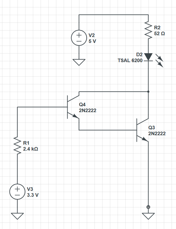
For the LED to light up properly, I assumed a forward current of 70mA and a voltage drop of 1.3V. The datasheet of the PN2222A states that at 70mA collector current, the saturation voltage \$V_{CE}\$ will be about 0.06V. So $$ R2 = \frac{5V - 1.3V - 0.06V}{0.07A} = 52\Omega $$ Lowest value of \$\beta\$ equals 10, resulting in a total minimum current gain of $$ \beta_{Total} = \beta^2 + 2\beta = 120 $$ \$I_{B}\$ is therefore $$ I_{B} = \frac{I_{C}}{\beta} = 583\mu A $$ So $$ R1 = \frac{3.3V - 1.62V}{583\mu A} = 2882\Omega $$ When I plugged in both voltage sources, the LED only glimmed lightly. I measured \$I_{C} = 42.4mA\$ which is definitely too low. For troubleshooting purposes I checked every voltage drop and one was far away from its theoretical value: \$V_{CE} = 0.7V\$.

Why is the real saturation voltage way higher than stated in the datasheet?

\$\endgroup\$
5
  • \$\begingroup\$ The LED only glimmed lightly in the wavelength area that your eyes are sensitive to, seeing as it is an IR transmitter. \$\endgroup\$
    – MrGerber
    Commented Jan 9, 2018 at 13:46
  • \$\begingroup\$ Well I couldn't even see it as its peak wavelength is at 940nm. However, my phone camera can see it and it was way less bright than my previous circuits without transistors. \$\endgroup\$
    – Overblade
    Commented Jan 9, 2018 at 13:51
  • \$\begingroup\$ But your camera is just marginally sensitive at 940nm, so the intensity you see with your phone camera is not by any means representative of what you would expect from a visible LED at similar power levels. \$\endgroup\$
    – MrGerber
    Commented Jan 9, 2018 at 14:06
  • \$\begingroup\$ It is sensitive enough to see a big difference between 40mA and 70mA. I know I can't judge the LED's power based on a camera. \$\endgroup\$
    – Overblade
    Commented Jan 9, 2018 at 16:00
  • \$\begingroup\$ The IR sensitivity is not dependent on the power of the light, but the wavelength (see example. You can of course see relative differences in signal, but my original statement was that whatever light intensity you observed was not an absolute indication on what was going on in the circuit. \$\endgroup\$
    – MrGerber
    Commented Jan 9, 2018 at 16:13

1 Answer 1

8
\$\begingroup\$

Why is the real saturation voltage way higher than stated in the datasheet?

Because you have configured your transistors as a darlington pair and no matter how hard Q4 is turned on it can only realistically shorts Q3's collector to Q3's base and, given that you need 0.7 volts on Q3's base to turn on Q3, you are left with Q3's collector at about 0.7 volts.

If Q4's collector were connected to 5 volts via an appropriate resistor (about 390 ohm) it would work closer to how you expect it to because you can source >10 mA from the 5 volt supply into Q3's base.

\$\endgroup\$
2
  • \$\begingroup\$ So I assume the saturation voltage is about 0.76V? \$\endgroup\$
    – Overblade
    Commented Jan 9, 2018 at 16:10
  • \$\begingroup\$ In this configuration the transistor isn't strictly speaking in saturation because base-collector cannot be forward biased because there is 0 volts across it. To enable several mA to flow through the collector, the base to emitter voltage has to be in the order of 0.6 volts or higher and it is difficult to calculate the point at which negative feedback causes equilibrium. I would always recommend using a decent simulation package (or LTSpice if you must) and try it out to see what voltage across C-E results. \$\endgroup\$
    – Andy aka
    Commented Jan 9, 2018 at 16:28

Your Answer

By clicking “Post Your Answer”, you agree to our terms of service and acknowledge you have read our privacy policy.

Not the answer you're looking for? Browse other questions tagged or ask your own question.