5
\$\begingroup\$

I'm building a circuit that I'd like to run at 8 MHz to begin with, but I want to be able to try it out at 10, 12, 16, 20, and, maybe, 25 MHz. I know that many microcontrollers have the ability to just plug a passive crystal into two pins and the µC will generate a square wave and pass it on to anything else it's connected to which needs a clock. What I'm wondering is if that functionality exists on its own in a nice, small package which will run at 5V. (I know I can build it using Schottky fast inverters and some capacitors and resistors, but I'd rather avoid all that external stuff if at all possible).

Alternatively, is there an easy way to generate a continuous range of frequencies of this magnitude (similar to what you can do with a 555 timer at lower frequencies)? I'm not too fussed about the frequency being particularly accurate, I'm pretty sure a 1% variability would be acceptable (2% seems like it's pushing it, but I'd certainly be willing to try it out)

Additionally, I've seen a suggestion to use a higher-frequency crystal and use a frequency divider to divide it by four. Is a T Flip-flop the best way to do that at these frequencies? (or, rather, two since one flip-flop is only going to halve the frequency). Does this advice make any sense given that I'm running this on a breadboard? (yes, I know, parasitic capacitance and all that, that's actually part of the reason I'm doing this experiment, I want to see the effect of this parasitic capacitance at the various frequencies and to see whether mounting the breadboard on a grounded copper plate makes any difference)

\$\endgroup\$
8
  • 1
    \$\begingroup\$ are you talking about a pll? \$\endgroup\$
    – PlasmaHH
    Commented Jul 4, 2018 at 15:29
  • \$\begingroup\$ All you need is an inverter and 2 small load caps. But for less stability a Schmitt Inverter and a 100k feedback trimpot with 10 pF on the input to gnd gives ~ 1MHz to max. Or use a CD4060 and <10pF caps or trim cap \$\endgroup\$
    – D.A.S.
    Commented Jul 4, 2018 at 15:36
  • 1
    \$\begingroup\$ Just take an 8-pin micro-controller than can run at the frequencies you want (but 25 MHz might be a problem) and tap its clock pin. \$\endgroup\$ Commented Jul 4, 2018 at 16:56
  • 2
    \$\begingroup\$ @immibis -- 6-DIP is a common package for optocouplers \$\endgroup\$ Commented Jul 5, 2018 at 2:50
  • 1
    \$\begingroup\$ Possibly you already know, but the most integrated version is just to use premade crystal oscillators (as opposed to crystal resonators). They usually have 4 pins and take in V+ and GND and output a nice square wave. \$\endgroup\$
    – jpa
    Commented Jul 5, 2018 at 6:10

4 Answers 4

14
\$\begingroup\$

enter image description here

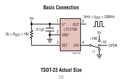
The LTC1799 can be programmed by a resistor and a link to produce a vast array of frequencies.

Is there a small (6-pin) DIP I can use to generate multi-MHz squarewave clocks with an external crystal?

  • It's certainly small
  • It's 5 pins not 6
  • It's not DIP but you want "small" and DIPs are not small in comparison to SM devices.
  • It doesn't use a crystal
\$\endgroup\$
5
  • \$\begingroup\$ I meant small as in not 8-or-more pins, not small as in surface mounted. the problem with surface mounted components is that they won't fit on a solderless breadboard. \$\endgroup\$
    – StarkRG
    Commented Jul 5, 2018 at 4:55
  • \$\begingroup\$ That is, however, exactly what I need, so I guess what I'll do is grab a breakout board in addition to that chip \$\endgroup\$
    – StarkRG
    Commented Jul 5, 2018 at 5:17
  • \$\begingroup\$ @StarkRG You can use a SOT23 break-out rather than look for TSOT23 \$\endgroup\$
    – Andy aka
    Commented Jul 5, 2018 at 9:23
  • 1
    \$\begingroup\$ Or just solder single stranded wires straight on :) \$\endgroup\$ Commented Jul 5, 2018 at 13:07
  • \$\begingroup\$ @DaveBoltman I just noticed how small this chip is, I don't think soldering longer pins to it is going to be a viable option: circuitbenders.co.uk/forsale/LTC/LTCmain.jpg \$\endgroup\$
    – StarkRG
    Commented Jul 5, 2018 at 18:08
12
\$\begingroup\$

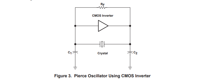
Yes, you can make a Pierce oscillator with one chip and a resistor and the two load capacitors, plus maybe a series resistor if the drive power is too great for your particular crystal.

enter image description here

The inverter must be an unbuffered type or it will likely do all kinds of undesirable things such as oscillating at two frequencies at once. Here is TI application note on doing just that. Some are indeed in '6 pin' or even 4 or 5-pin packages (eg. 0.8mm or 0.9mm square package so pretty darned small).

This is basically what is inside a microcontroller crystal circuit, though usually Rf is internal, and (rarely) the capacitors are inside, so it's essentially no more parts (or just a resistor, something like 1M). You should calculate the capacitors for the appropriate load capacitance of the crystal you have in mind, but if you're off a bit, it will usually just oscillate at a slightly less accurate frequency.

You can use something like an 74AC74 to divide down the output (up to about 125MHz), just connected the D input to /Q.

\$\endgroup\$
3
\$\begingroup\$

If you want a more integrated solution...

I would look at a Si514 for this task. It's available in a fairly small (5x7mm) leadless 6-contact SMT package with a bypass capacitor for the only external component, and can be programmed to any frequency within its operating range over I2C. There is one caveat though, and that is that the I2C programming is volatile, although that may not matter for an experimental rig like yours.

\$\endgroup\$
-1
\$\begingroup\$

Perhaps you could compromise and place a tiny FPGA onto a 6 pin carrier PCB.

The DIPSY project could point you in the correct direction. It might even be possible to program it to be a variable frequency generator. Best case scenario it could even handle all the system functionality in the logic code.

https://hackaday.io/project/6592-dipsy/details

\$\endgroup\$
4
  • 1
    \$\begingroup\$ That part is unsuitable to the task. While some iCE40 parts have a PLL block, the SWG16 package used on that board does not. \$\endgroup\$
    – user39382
    Commented Jul 4, 2018 at 23:03
  • \$\begingroup\$ @duskwuff, This was merely a suggestion for a starting point, there is insufficient information in the OPs question to give an exact answer. The CM49 ucBGA type has more pins and a PLL and is smaller than a 6 pin DIL footprint (under 3x3mm). The suggested link was there to demonstrate the DIY possibilities of using FPGA solutions. \$\endgroup\$
    – KalleMP
    Commented Jul 5, 2018 at 7:57
  • \$\begingroup\$ An FPGA is really not a good solution for this problem in general. All you need is a PLL; the rest of the logic is wasted. \$\endgroup\$
    – user39382
    Commented Jul 5, 2018 at 8:04
  • \$\begingroup\$ @duskwuff In all fairness we don't know what this problem is specifically or in general. He is building a circuit that may consist of a dozen logic ICs that can all hide inside his clock generator if he is using an FPGA for this purpose. The FPGA may be useful simply as a way to control the PLL with a button or IO pins, we just don't know but have no reason to assume the worst just yet. \$\endgroup\$
    – KalleMP
    Commented Jul 5, 2018 at 8:08

Your Answer

By clicking “Post Your Answer”, you agree to our terms of service and acknowledge you have read our privacy policy.

Not the answer you're looking for? Browse other questions tagged or ask your own question.