1
\$\begingroup\$

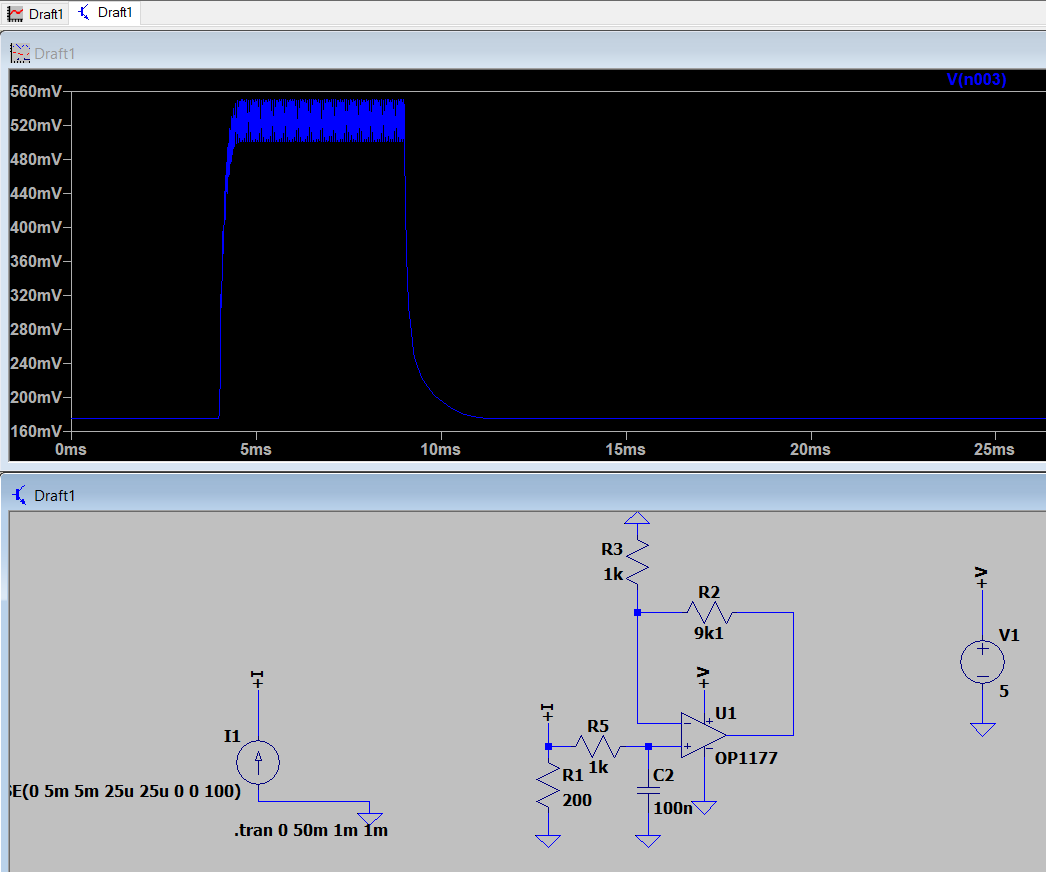
I am looking at using the OP1177 to act as an active low pass filter. I need to smooth out a 20kHz signal burst with a minimum of 50 cycles to reach a voltage on the output to interrupt an microcontroller.

I have tuned my circuit succesfully first with the passive RC and obtained the required rise time. RC passive

However when I use the op-amp I get a very big offset voltage at the input. I have a gain of ten but I get a minimum input voltage of ~160mV. The input offset voltage of the op-amp is 60uV maximum so it can't be that. Does anyone have any idea what parameter or method of analysis I should be looking out to defeat this problem? I am going to change to a LT1001 op-amp which runs without this problem in simulations but any ideas would be greatly appreciated!

Regards,

enter image description here

\$\endgroup\$

2 Answers 2

2
\$\begingroup\$

The OP1177 data sheet says that the input voltage range for the device is -3.5 volts to + 3.5 volts when powered from a +/- 5 volt supply. This means any input closer to the op-amps negative rail than 1.5 volts is going to hit problems. Your negative rail is 0 volts and your positive rail is 5 volts hence the usable input range is from +1.5 volts to +3.5 volts.

I have a gain of ten but I get a minimum input voltage of ~160mV

Your signal tries to fall to 0 volts and the op-amp will possibly restrict that from happening due to exceeding the specified input voltage range at the negative rail. All bets are off when you try and do things like this.

In addition to this the data sheets informs that the output signal can only get to within about 1 volt of the negative rail (or +1 volt in your set-up).

I am going to change to a LT1001 op-amp which runs without this problem in simulations

That device will have similar problems - it's input range gets to within 1 volt of the negative rail typically but is not guaranteed to operate under all circumstances unless it gets no closer than 2 volts. The output voltage swing is guaranteed to within 3 volts of the rails but no closer.

\$\endgroup\$
2
  • \$\begingroup\$ So would a single supply rail to rail op amp be the solution? \$\endgroup\$ Commented Dec 10, 2018 at 17:28
  • \$\begingroup\$ @ConfusedCheese an op-amp that includes the most negative rail in the input signal range is the better choice because there are more of them but also, the gain of ten requires a supply voltage that is higher than 5 volts. The obvious (but sometimes less convenient) fix is to use a +/- 10 volt rail. Or a neg rail that is -3 volts and a pos rail that is about 8 volts would work with most op-amps. R2R op-amps can never really get the output down to the neg rail or up to the pos rail. \$\endgroup\$
    – Andy aka
    Commented Dec 10, 2018 at 17:37
0
\$\begingroup\$

An input current of 5mA (that´s what I can derive from the diagram) causes a voltage across R=200 ohm of 5E-3*200=1V. Hence, there is an input voltage of 1V at the non-inv. node - and the gain is 10. Therefore, we can expect a DC output of +10V .

\$\endgroup\$
1
  • \$\begingroup\$ The actual signal into the +Vin pin is what is shown in the blue waveform in the top diagram i.e. about 500 mV. It'll still hit the output end-stops though. \$\endgroup\$
    – Andy aka
    Commented Dec 10, 2018 at 17:21

Your Answer

By clicking “Post Your Answer”, you agree to our terms of service and acknowledge you have read our privacy policy.

Not the answer you're looking for? Browse other questions tagged or ask your own question.