2
\$\begingroup\$

I'm a beginner to circuits. Unlike many other questions, my circuit involves a parallel circuit with a LED on one path but a resistor on the other, as shown in the picture.

Q1: assuming the LED has a 3V voltage drop, does this mean R1 will have to drop 6V even if the LED is on parallel?

Q2: If I know the voltage drop of R1, just how can I compute the CURRENT that will go through each path? Since the LED has a constant voltage drop but R2 has a constant resistance I don't think I can use any laws I know so far — LED's and resistors are not the same things. I only know how to compute the current if both were LED's or resistors.

P.S. This sort of looks like a voltage divider, but the problem is that the LED does not have a separate ground but is connected back to the same battery, which then makes the circuit parallel and I'm assuming thing work differently. (And it did in my simulator)
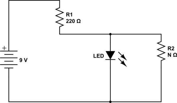
schematic

simulate this circuit – Schematic created using CircuitLab

\$\endgroup\$
4
  • \$\begingroup\$ Are you familiar with how to take a resistor divider and turn it into its Thevenin equivalent? (Because you do have a resistor divider there.) \$\endgroup\$
    – jonk
    Commented Apr 8, 2019 at 2:26
  • \$\begingroup\$ @jonk you mean equivalent circuit? Not since I have no way to combine resistors and a LED \$\endgroup\$
    – dvx2718
    Commented Apr 8, 2019 at 2:28
  • \$\begingroup\$ You can ignore the LED for the purposes of handling the resistor divider. Then, with that worked out, you can simply re-add the LED to the circuit and work things out from there. Just use your finger to cover up the LED so it's not part of the circuit. Work out the voltage at the resistor divider. Work out the effective resistance of the two divider resistors, too. Then lay out the new circuit with the thevenin voltage source, the thevenin resistance, and the LED. Do you need me to show you how? Or does that make sense, already? \$\endgroup\$
    – jonk
    Commented Apr 8, 2019 at 2:28
  • \$\begingroup\$ And neither diodes nor LEDs really have a constant voltage drop. They will have a voltage drop that rises or falls a little depending upon the actual current through them (and the details of the specific LED you have in hand, of course.) However, if you don't (or can't) worry about those details and just want to treat them has having a fixed voltage drop, everything still works out okay. But it's more theoretical then, than actual. \$\endgroup\$
    – jonk
    Commented Apr 8, 2019 at 2:35

2 Answers 2

1
\$\begingroup\$

You can follow jonk's approach and you will end with a Thevenin voltage and a source resistance.

If you model the LED as an otherwise perfect diode with a 3V drop you will have two possible conditions:

  1. The Thevenin voltage is less than 3V. In that case you ignore the LED (and, of course, it will be 'off').

  2. The Thevenin voltage is greater than 3V. In that case you can calculate the current as the (Vthev - 3V) divided by the Thevenin resistance


Or you could be lazy and assume the LED is on, meaning the current from the supply is indeed 6V/220 ohms. The current through the parallel resistor is 3V divided by the parallel resistor. The current through the LED is the difference. If that current turns out to be negative, then your initial assumption was wrong.

The advantage of doing it "properly" is that you can use a graphical load line method, or a nonlinear equation solving method to find the LED current if you model it using the data sheet curves or the Shockley diode equation respectively.

On the other hand, if it's an exam question I think I'd opt for the cheap and dirty method.

\$\endgroup\$
1
  • \$\begingroup\$ It's possible that this is an exam/homework question because such circuit doesn't make any sens. \$\endgroup\$
    – Fredled
    Commented May 27, 2020 at 21:48
0
\$\begingroup\$

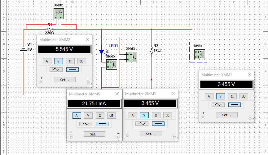
1)The LED is parallel to the series combination of voltage(9V) and the 220 ohm resistor. In the below simulation, the LED has a PD of 3.345 volts and hence the voltage across R2(1k ohm) is also the same. Hence the voltage 220 ohm is 9 - 3.345 = 5.545 volts. 2) As we know the voltage across R1 (5.545 V), the current through it is 5.545 / 220 = 25.204 mA (approx.). Next the voltage across 1k ohm is 3.345 V and the current is 3.345/1000 = 3.345 mA. By simple KCL, current through the LED is 25.204 - 3.345 = 21.8 mA (approx. )

Simulation

\$\endgroup\$

Your Answer

By clicking “Post Your Answer”, you agree to our terms of service and acknowledge you have read our privacy policy.

Not the answer you're looking for? Browse other questions tagged or ask your own question.