0
\$\begingroup\$

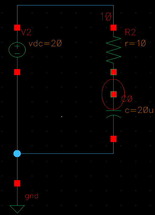
I am trying to do a simple RC transient simulation in Cadence virtuoso. Please see the circuit below:
enter image description here

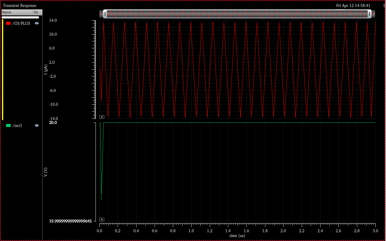
I am trying to see the transient current and voltage of the capacitor being charged,however I got the following simulation result:
enter image description here

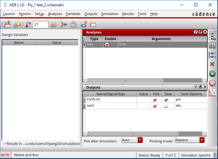
where /net3 is the capacitor voltage and CO/plus is the capacitor current. This looks totally incorrect, and I have my simulation configuration as:
enter image description here

Could anyone help me figure out the issue? Thanks!

\$\endgroup\$
4
  • \$\begingroup\$ One thing I see is that your .TRAN time appears to be limited to \$3\:\mu\text{s}\$, which is far from the RC time constant of \$200\:\mu\text{s}\$. Are you looking to see the typical RC exponential curves for voltage and current? If so, you may want to set the .TRAN simulation time to about \$1\:\text{ms}\$ or so. (I've no idea if this will help your situation. It's just that the time period seems so short that perhaps your simulator is behaving badly, numerically.) LTspice has no problem showing the exponential curves, by the way. \$\endgroup\$
    – jonk
    Commented Apr 12, 2019 at 19:24
  • \$\begingroup\$ Thank you Jonk. It's weird because the voltage already converge to 20V at <0.1us. But I tried 1ms as well, I still cannot see the expected curve. \$\endgroup\$
    – Leey
    Commented Apr 12, 2019 at 19:32
  • \$\begingroup\$ I can't actually help you with Cadence Virtuoso. I simply don't have nor use it. However, I can show you an image from LTspice. Is that what you are looking for? Note the UIC parameter to the .TRAN that I used? Maybe something there helps. \$\endgroup\$
    – jonk
    Commented Apr 12, 2019 at 19:47
  • \$\begingroup\$ Thanks for help Jonk! This is exactly what I expect, I consulted Cadence forum, and I learnt that to do such a transient simulation with a DC source, the 'initial state' of capacitor has to be set to 0V, otherwise, the initial state of capacitor will have 20V by default. \$\endgroup\$
    – Leey
    Commented Apr 15, 2019 at 14:02

1 Answer 1

0
\$\begingroup\$

Your observation (and the comments you received at the Cadence forum) is perfectly normal for Spice. Normally, Spice performs an "initial transient solution" (aka ITS) step to find a DC (steady state) solution before starting the transient analysis at \$t=0\$. In your case, Spice found a steady state solution, which was that the voltage on the capacitor was \$20\:\text{V}\$, and it then presented that result to you.

Spice could have been designed so that it didn't do this initial step. But I think earlier work simulating electronic circuits showed that this ITS step was the preferred default mode. Of course, they also knew they needed to provide a way to avoid that step. So, to override the default ITS step, they provided a UIC keyword option on the .TRAN card.

When you use UIC, the initial value of every single energy storage device (whether voltage or current) is treated as zero -- except those devices where you explicitly provide an .IC statement. (Each .IC card sets up constraints on the solver for the initial conditions that it is forced to apply before starting the run.)

There's perhaps one more thing to note, here. If you are having trouble finding a desired steady state operating point with Spice (such as with some bistable circuits), it may be because Spice also assumes that all node voltages start out at \$0\:\text{V}\$ (relative to your ground reference, where ever you placed it.) In such cases, you can use .NODESET to establish node voltages to help Spice find a specific DC solution. (Just don't use .NODESET to set the exact value you get from a previous run! Instead, just set the node voltage "near" to where you think it will arrive, later, and let Spice find the DC solution for you.)
\$\endgroup\$

Your Answer

By clicking “Post Your Answer”, you agree to our terms of service and acknowledge you have read our privacy policy.

Not the answer you're looking for? Browse other questions tagged or ask your own question.