You really, really need to understand why a resistor divider can be reduced to a voltage source and a series resistor.
If you don't understand it, don't believe it, don't have a feel for it, then you won't apply it. Or, if you do, you'll always be unsure and nervous about it. That kind of worry has to be driven out of you. You need to have confidence in the Thevenin equivalent of a resistor divider. The idea needs to be so deeply buried inside your bones that you will never question it, again. You will just "know" and be confident in that fact.
Let's proceed...
Thevenin Voltage of a Resistor Divider
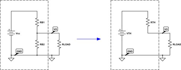
A resistor voltage divider looks like this:

simulate this circuit – Schematic created using CircuitLab
On the left side we have two resistors in series between a power supply. What I'd like to know is what is the voltage at \$+V_\text{TH}\$. But when I ask that question, I have to say, "relative to what other location in the circuit?" So I've labeled another spot (node) called \$-V_\text{TH}\$, which identifies the location I've picked as the "relative to" answer. So now I'm asking, "What is the voltage at \$+V_\text{TH}\$ with respect to the voltage at \$-V_\text{TH}\$?"
In your transistor circuit, \$-V_\text{TH}\$ is ground. So on the right side, I'm renaming \$-V_\text{TH}\$ to "GND." There's no harm in this and it doesn't change the circuit. It just renames a node. Which is harmless. (Well, you don't get to rename a node to the same node name given to a different node, of course. And so you only get to have one GND node.) So I think you can easily see that the right side is the same as the left. I also decided to remove the +-sign and therefore rename the mid-point voltage as \$V_\text{TH}\$. (It's just a variable, now.)
I'm taking this slowly for a reason. I think you already know how to calculate \$V_\text{TH}\$ since it is hard to imagine you haven't had to work that out, just yet. But I want to make sure that the ground-work is laid out carefully, too, and that you can follow along.
(NOTE: By convension, any node labeled "GND" is assumed to be the "default reference point," whenever anyone is talking about the voltage at some other place in the circuit. We just "assume" that's the "relative to" location. So now, I can just ask "What the voltage at \$V_\text{TH}\$?" and you are then supposed to insert in your head "with respect to GND" in your own head. It's just a "common" that is always inferred whenever anyone talks about voltages without explicitly saying what it is in reference to. (Voltages are always a "voltage here with respect to a voltage there," as they are always relative measurements and have no absolute meaning.)
Now, as I proceed below, I want you to temporarily "forget" the fact that your circuit above has a BJT base also connected up. For now, we don't want to know about this and don't want to think about it. We'll get back to it, soon enough. So just hold your horses, for now.
With that in mind, we can work out the voltage at \$V_\text{TH}\$. We know the current through the series circuit is \$I_\text{TOT}=\frac{V_\text{CC}}{R_{\text{B}_1}+R_{\text{B}_2}}\$. But \$I_\text{TOT}\$ through \$R_{\text{B}_2}\$ will cause a voltage difference from one end to the other end of the resistor of \$V_\text{TH}=I_\text{TOT}\cdot R_{\text{B}_2}=V_\text{CC}\cdot\frac{R_{\text{B}_2}}{R_{\text{B}_1}+R_{\text{B}_2}}\$. This is a classic form for computing the voltage in the middle of a resistor divider pair.
This is the often simply called the Thevenin voltage, \$V_\text{TH}\$, for a resistor divider (with that implied reference to GND, of course.)
So, we have:
$$V_\text{TH}=V_\text{CC}\cdot\frac{R_{\text{B}_2}}{R_{\text{B}_1}+R_{\text{B}_2}}$$
Thevenin Resistance of a Resistor Divider
There is also a Thevenin resistance. This is a little trickier to gather up. Many will just tell you about linearity and superposition. But then this is just two more things I have to explain, in detail. And they are abstract and probably require a calculus viewpoint, anyway.
Let's add a load to the above circuit, as follows:

simulate this circuit
Note that I've drawn a box around our resistor divider circuit on the left side. \$R_\text{LOAD}\$ doesn't "know" what's in there. All it knows is that there is a connection point and ground that it will attach to. But suppose we want to find out if the idea found on the right side could be used. We already know how to compute \$V_\text{TH}\$, so the only remaining question is if we can find an expression for \$R_\text{TH}\$ that doesn't depend upon \$R_\text{LOAD}\$. If it does depend upon \$R_\text{LOAD}\$, we are screwed. But if the expression cancels things out such that \$R_\text{LOAD}\$ magically disappears, then we may have something.
Let's start with the easier right side schematic. Find the right-side is \$I_\text{LOAD}=\frac{V_\text{TH}}{R_\text{TH}+R_\text{LOAD}}\$. The left side schematic is a little more complex. Here, will have the left-side is \$I_\text{LOAD}=\frac{V_\text{O}}{R_\text{LOAD}}\$. But we also have \$V_\text{O}=V_\text{CC}\cdot\frac{R_{\text{B}_2}\mid\mid R_\text{LOAD}}{R_{\text{B}_1}+R_{\text{B}_2}\mid\mid R_\text{LOAD}}\$. Clearly, both these left-side and right-side calculations for \$I_\text{LOAD}\$ should be equal to each other. So we can say:
$$\begin{align*}
\frac{V_\text{TH}}{R_\text{TH}+R_\text{LOAD}}&=\frac{V_\text{CC}\cdot\frac{R_{\text{B}_2}\mid\mid R_\text{LOAD}}{R_{\text{B}_1}+R_{\text{B}_2}\mid\mid R_\text{LOAD}}}{R_\text{LOAD}}\\\\
V_\text{CC}\cdot\frac{R_{\text{B}_2}}{R_{\text{B}_1}+R_{\text{B}_2}}\cdot\frac{1}{R_\text{TH}+R_\text{LOAD}}&=\frac{V_\text{CC}\cdot\frac{R_{\text{B}_2}\mid\mid R_\text{LOAD}}{R_{\text{B}_1}+R_{\text{B}_2}\mid\mid R_\text{LOAD}}}{R_\text{LOAD}}
\end{align*}$$
You can see, at least for a start, that \$V_\text{CC}\$ cancels out. But I'll save you the trouble of the algebra and simply say that if you re-work the above equation, solving for \$R_\text{TH}\$, you will find:
$$R_\text{TH}=\frac{R_{\text{B}_1}\cdot R_{\text{B}_2}}{R_{\text{B}_1}+R_{\text{B}_2}}$$
Using calculus (I'll avoid the details here), I'd instead just solve the following (the negation is due to the fact that I know if the load current increases that the output voltage decreases):
$$\begin{align*}
R_\text{TH}&=-\frac{\text{d}\, V_\text{O}}{\text{d}\,I_\text{LOAD}}=\frac{R_{\text{B}_1}\cdot R_{\text{B}_2}}{R_{\text{B}_1}+R_{\text{B}_2}}
\end{align*}$$
Experimental Validation
Suppose \$V_\text{CC}=5\:\text{V}\$, \$R_{\text{B}_1}=1\:\text{k}\Omega\$, and \$R_{\text{B}_2}=4\:\text{k}\Omega\$. We can now compute \$I_\text{TOT}=\frac{5\:\text{V}}{1\:\text{k}\Omega+4\:\text{k}\Omega}=1\:\text{mA}\$ and therefore that \$V_\text{TH}=4\:\text{k}\Omega\cdot 1\:\text{mA}=4\:\text{V}\$. From the above work, we would also now say that \$R_\text{TH}=1\:\text{k}\Omega\mid\mid 4\:\text{k}\Omega=800\:\Omega\$.
So this is what our above theory says is the Thevenin equivalent circuit:

simulate this circuit
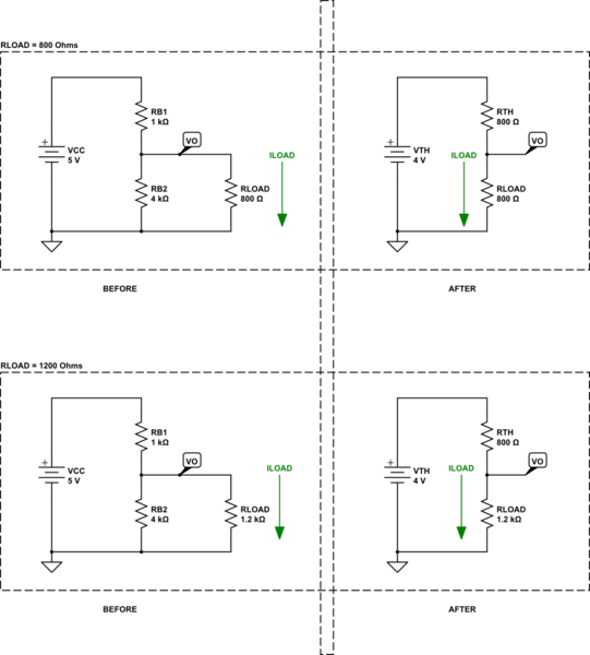
Let's consider two different load resistor values that we'll place between the \$+V_\text{TH}\$ output wire and the GND wire. Suppose we use \$R_\text{LOAD}=800\:\Omega\$ and \$R_\text{LOAD}=1200\:\Omega\$. We'll analyze the first circuit and then we'll analyze the "Thevenin equivalent" circuit for both cases. So we'll have four results and we'll compare them.

simulate this circuit
On the upper-left, we have \$800\:\Omega\mid\mid 4\:\text{k}\Omega=\frac23\:\text{k}\Omega\$ that is in-series with \$1\:\text{k}\Omega\$. So the total current from the power supply will be \$\frac{5\:\text{V}}{1\:\text{k}\Omega+\frac23\:\text{k}\Omega}=3\:\text{mA}\$. This means that \$R_1\$ will drop \$1\:\text{k}\Omega\cdot 3\:\text{mA}=3\:\text{V}\$, leaving \$+V_\text{TH}=5\:\text{V}-3\:\text{V}=2\:\text{V}\$. From this, we find that \$I_\text{LOAD}=\frac{2\:\text{V}}{800\:\Omega}=2.5\:\text{mA}\$.
On the upper-right, we have a total current of \$\frac{4\:\text{V}}{800\:\Omega+800\:\Omega}=2.5\:\text{mA}\$. Note that all of the total current is flowing through \$R_\text{LOAD}\$. So this matches up with what we just calculated for the upper-left circuit.
On the lower-right, we have \$1.2\:\text{k}\Omega\mid\mid 4\:\text{k}\Omega=923 \frac1{13}\:\Omega\$ that is in-series with \$1\:\text{k}\Omega\$. So the total current from the power supply will be \$\frac{5\:\text{V}}{1\:\text{k}\Omega+923 \frac1{13}\:\Omega}=2.6\:\text{mA}\$. This means that \$R_1\$ will drop \$1\:\text{k}\Omega\cdot 2.6\:\text{mA}=2.6\:\text{V}\$, leaving \$+V_\text{TH}=5\:\text{V}-2.6\:\text{V}=2.4\:\text{V}\$. From this, we find that \$I_\text{LOAD}=\frac{2.4\:\text{V}}{1.2\:\text{k}\Omega}=2\:\text{mA}\$.
On the lower-right, we have a total current of \$\frac{4\:\text{V}}{800\:\Omega+1.2\:\text{k}\Omega}=2\:\text{mA}\$. Note that all of the total current is flowing through \$R_\text{LOAD}\$. So this matches up with what we just calculated for the lower-left circuit.
I think you can see, at least from these examples anyway, that it appears this "trick" works.
Applying the Thevenin Equivalent to your Circuit
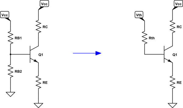
If you think closely about your circuit, you'll see the following as true:

simulate this circuit
Just applying KVL now, we can find:
$$V_\text{TH}-I_\text{B}\cdot R_\text{TH}-V_\text{BE}-I_\text{E}\cdot R_\text{E}=0\:\text{V}$$
But as \$I_\text{B}=\frac{I_\text{E}}{\beta+1}\$, this can be re-written as:
$$V_\text{TH}-\frac{I_\text{E}}{\beta+1}\cdot R_\text{TH}-V_\text{BE}-I_\text{E}\cdot R_\text{E}=0\:\text{V}$$
And solved for \$I_\text{E}\$ as:
$$I_\text{E}=\frac{V_\text{TH}-V_\text{BE}}{R_\text{E}+\frac{R_\text{TH}}{\beta+1}}$$
Or, alternately, for \$I_\text{B}\$ as:
$$I_\text{B}=\frac{V_\text{TH}-V_\text{BE}}{R_\text{TH}+\left(\beta+1\right)\cdot R_\text{E}}$$
The above assumes that the BJT is in active mode and isn't saturated by the circuit that surrounds it. (But this is easy to test. If you compute \$V_\text{C}=V_\text{CC}-\beta\cdot I_\text{B}\cdot R_\text{C}\lt V_\text{B}\$ then it is in some level of saturation.)


