0
\$\begingroup\$

I am trying to read a huge number of digital inputs (129 to 800 and maybe more) at the same time. the sampling rate should be around 500K samples per second but I only need to read one of these inputs if there is a signal change (interrupt?). I am stuck at this for a long time and would really appreciate the help.

  • should I use 16 bit PISO shift-registers IC and a simple MCU but it seems that I will have to check every bit looking for a high signal?.

  • should I use an IO expander IC with SPI such as interface such as MCP23S17 but usually these have 3 bit address which mean I only could get away with 16*8=128 inputs. Another IO expander with greater IOs is MAX7301 but I am not sure how to use multiple ones and if it would affect the performance.

  • should I move to an FPGA for this sort of jobs given that I never touched one but I am ready confront my fears.

  • will multiplexers work or will they have their limits

  • could a hardware cascade of ICs solve this issue so I only recive the address of the changing bit with timestamp but how?

it is important to note that I need to keep the sampling time high in order to capture any change in one or at most 2 pins. please point me to the right direction as I am clueless and don't know what to do.

\$\endgroup\$
12
  • \$\begingroup\$ What is this "timestamp" you refer to? What do you intend to do with the information about a pin change once you have it...does it need to be transmitted or logged? If so, how? \$\endgroup\$ Commented Jun 14, 2019 at 18:08
  • \$\begingroup\$ Why is breaking out the two pins you need at high speed, and handling the others differently, not an option? \$\endgroup\$ Commented Jun 14, 2019 at 18:42
  • 1
    \$\begingroup\$ @ScottSeidman: Sounds like it could be any two of the 800. Not always the same two. Like, the states of any of the 800 could change in any sampling period, but never more than two will change in a sampling period. \$\endgroup\$
    – JRE
    Commented Jun 14, 2019 at 18:48
  • 2
    \$\begingroup\$ I think you need to do some math, first. Sampling 800 inputs at 500000 samples per second gets you 400000000 samples per second - that's 400 million samples. You'll not be reading that through any IO expander I've ever heard of. \$\endgroup\$
    – JRE
    Commented Jun 14, 2019 at 18:53
  • 5
    \$\begingroup\$ Monitoring hundreds of I/O for state changes at 500 kHz seems like an FPGA task to me. However, there's probably an XY problem in here as well. It'd be very useful to have additional info on what exactly you're trying to detect \$\endgroup\$ Commented Jun 14, 2019 at 18:55

2 Answers 2

4
\$\begingroup\$

A microcontroller with lots of pins as an intelligent I/O expander could be more cost-effective than an FPGA.

An STM32H743BIT6 has for example 168 I/O pins, let's say 8 of them are needed for communication and debugging, leaving 160 inputs for the application. These pins are arranged in 11 ports of 16 bits each. The controller runs on 400 MHz, so there'd be about 72 clock cycles to read and evaluate each port. There is 64k code memory with 0 wait state even at full speed, it seems plausible with some careful assembly coding.

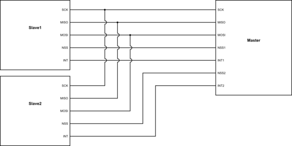
You can connect a couple of these controllers as SPI slaves to a master MCU.

schematic

simulate this circuit – Schematic created using CircuitLab

Each slave would scan its inputs continuously, and signal on the INT output whenever there is a change, then the master can poll that slave for the pin number(s). As a crude means of avoiding race conditions, the slave could suspend processing the inputs until the master acknowledges it by reading the SPI buffer.

\$\endgroup\$
3
\$\begingroup\$

Forgive my ignorance, but if a regular IC won't do it. could you point me to how to do it using an FPGA. which kit has this many inputs? a general idea of how to do it would be greatly appreciated.

Unfortunately what you ask falls under "design services" which is not what we offer here. So I will only some give guidance.

You can get FPGAs with up to 1400 pins. The bigger ones (>800 pins) are not cheap. I had a quick look and you are talking $1200 plus. You hardly need any logic (2000 registers or so) so it may be cheaper to use several smaller FPGAs.

Use a clock (500KHz or higher) to register each input and make an edge detector. Every decent HDL designer knows how to do that. As soon as an edge is seen store a counter value.

With such a larger number of pins I would divide the task in pin-groups and add some pipelining logic to find the two lowest counter values and subtract to get the difference. This is also beneficial if you use multiple smaller FPGAs.

This is only an outline, the actual task may be more complex because we don't know the details and every experienced engineer knows that the devil is in the detail.

\$\endgroup\$
2
  • \$\begingroup\$ With so many inputs you may need to use multiple FPGAs, in which case you should try using an FPGA module rather than FPGA chips (daunting to implement) or a FPGA dev board (too much extra stuff size for the number of inputs you need). I like the modules made by Trenz. The TE0714 has the best bang and number of I/O for the buck, but the TE0725 has can hold the largest designs for the buck and is thru-hole so can be breadboarded somewhat. \$\endgroup\$
    – DKNguyen
    Commented Jun 14, 2019 at 21:09
  • 1
    \$\begingroup\$ Also, FPGAs can do multiple thing simultaneously so you may end up with a more manageable design by have a single FPGA control multiple multiplexers. As long as the FPGA can scan through all the lines on a multiplexer in a time interval less than your required timing accuracy you will be fine. The FPGA would use the same common signals to switch each mux (when one mux switches to the channel X, all the muxes switch to channel X). Increasing the number of muxes and reducing the number of signals per mux approaches the a non-multiplexed approach where each line has a direct FPGA connection \$\endgroup\$
    – DKNguyen
    Commented Jun 14, 2019 at 21:10

Your Answer

By clicking “Post Your Answer”, you agree to our terms of service and acknowledge you have read our privacy policy.

Not the answer you're looking for? Browse other questions tagged or ask your own question.