3
\$\begingroup\$

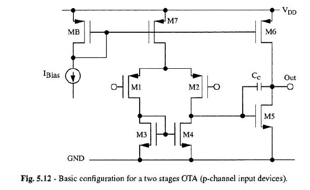
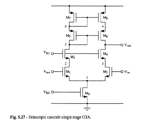
I'm studying the circuits which are used to implement operational amplifiers. For example, I've studied the two stages amplifier (in which the first stage is a differential amplifier with differential to single ended transformation, the second stage is an inverter with active load), the telescopic cascode, and other circuits. Here a picture of these circuits:

enter image description here

enter image description here

I noticed that in all of these circuits the book I read always assumes a differential input, that is two (small) signals with the same DC value and amplitudes which are equal and opposite. As a consequence of the superposition principle and of the symmetry of these circuits, we can divide the circuit into two parts and all the nodes on the axis of symmetry become ac grounds. This simplifies the analysis, in particular it becomes easier to find the differential gain.

The question is: who says that, when I close these circuits with feedback, I will have at the inverting and at the non-inverting terminals a perfect differential input? It appears as if the book assumes that I will get for sure this situation. In other words, who says that, when I close the circuit with feedback, I get the same differential gain (if I close the circuit with feedback, in general I don't have two perfect differential signals, and as a consequence I am not allowed to divide by symmetry the circuit and to consider all the nodes on the axis of symmetry as ac grounds)?

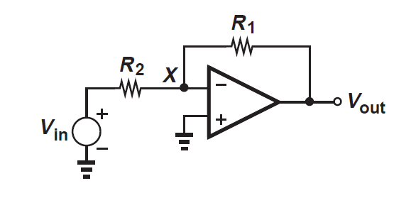
For example, let us assume that I use one of these circuits to implement the classic inverting configuration:

enter image description here

You can see that the non-inverting terminal is fixed at ground, then it is impossible to have a differential input for the op-amp.

Thank you

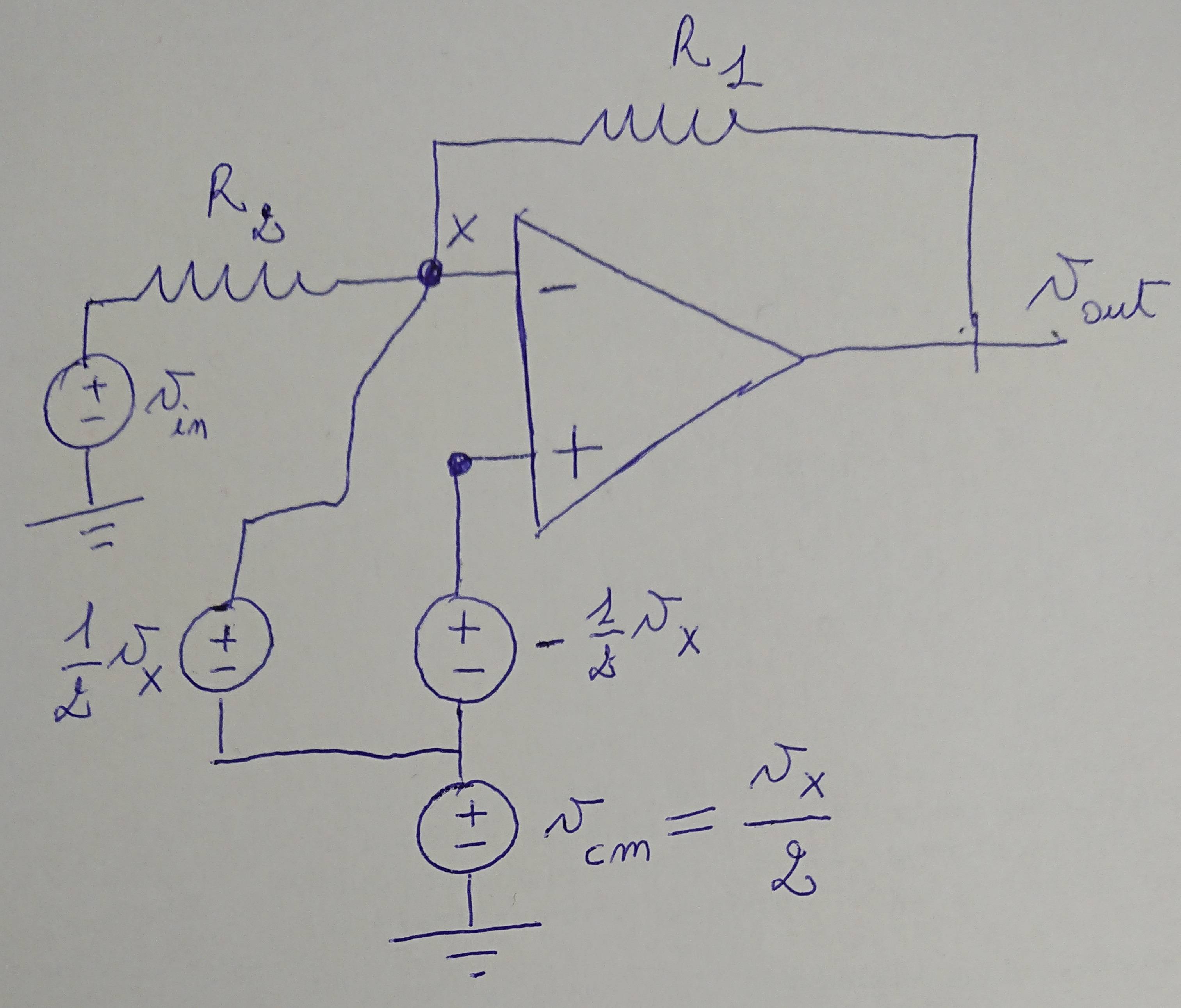
Image added for the comment:

enter image description here

\$\endgroup\$
1
  • \$\begingroup\$ Also consider at UGBW, the forward gain is ONE Thus for 1 volt output, you need ONE volt input, and the distortion will be huge. \$\endgroup\$ Commented Jul 22, 2019 at 15:19

4 Answers 4

3
\$\begingroup\$

I noticed that in all of these circuits the book I read always assumes a differential input, that is two (small) signals with the same DC value and amplitudes which are equal and opposite. ... The question is: who says that, when I close these circuits with feedback, I will have at the inverting and at the non-inverting terminals a perfect differential input?

If you have any two input voltages, \$V_+(t)\$ and \$V_-(t)\$, you can decompose them into differential and common mode signals

$$V_d(t) = V_+(t)-V_-(t)$$ $$V_{cm}(t) = \frac{V_+(t)+V_-(t)}{2}$$

and if you know the differential and common mode parts you can re-construct the two independent single-ended signals

$$V_+(t) = V_{cm}(t) + \frac{1}{2}V_d(t)$$ $$V_-(t) = V_{cm}(t) - \frac{1}{2}V_d(t)$$

So regardless of what the actual input signals into your op-amp are, you can analyze them (using superposition, as you mentioned) as differential and common-mode signals.

And, if you have a well-designed op-amp, you probably already learned that the common mode gain is very small, particularly in comparison to the differential gain. So, at least for hand calculation, it's quite reasonable to simply ignore the common-mode component of the input and calculate the output only from the differential part of the input.

You can see that the non-inverting terminal is fixed at ground, then it is impossible to have a differential input for the op-amp.

This is not correct. If there is a difference between the two inputs, you have a differential component in your input signal. In your example, with \$V_+=0\$, you have \$V_d = -V_-\$ (and also \$V_{cm}=V_-/2\$).

\$\endgroup\$
3
  • \$\begingroup\$ Let me sum up: 1) since the differential gain dominates with respect to the common mode gain, I can neglect the common mode gain and I am allowed to consider only the differential gain. 2) As a consequence, considering an op-amp with negative feedback, vout is just given by Ad*(v+ - v-) and, assuming Ad very large, the difference between v+ and v- becomes very very small. 3) If I wanted to be more precise, I should apply superposition principle to the circuit in the last image I added in the question, sum up the contributions coming from the differential signals and from the common mode signal \$\endgroup\$
    – Stefanino
    Commented Jul 23, 2019 at 8:23
  • \$\begingroup\$ Not sure about your added diagram. Are those supposed to be sources or meters? And what is \$v_x\$? \$\endgroup\$
    – The Photon
    Commented Jul 23, 2019 at 14:21
  • \$\begingroup\$ They are voltage sources; vx is the generic voltage at the inverting terminal (I applied the substitution principle: if I know the voltage in a given point, then I am allowed to place a voltage source with that voltage value). I wanted to decompose the voltage signals at the input terminals of the op-amp as a common mode and a differential mode \$\endgroup\$
    – Stefanino
    Commented Jul 23, 2019 at 17:06
4
\$\begingroup\$

The op amp doesn't know that the non-inverting input is tied to ground. The op amp only sees that the inverting input is a tiny bit above or below the voltage at the non-inverting input (assuming that we have negative feedback).

It's the negative feedback that forces the two inputs to be very close together.

So the op amp acts as a difference amplifier, amplifying the small difference in voltage between the two inputs. Because we have added negative feedback we have constrained the entire circuit to act as a linear amplifier with a gain determined by the resistor values.

\$\endgroup\$
3
\$\begingroup\$

To simplify the following analysis I've assumed that the op amp is ideal (zero input offset voltage etc). Also shouldn't M5 in Fig. 5.12 be bipolar device. In the following description of operation I have assumed that it is.

Lets start by assuming that both op amp inputs are exactly at zero volts, the output is at a voltage which puts the negative input exactly at ground potential. In this situation there would be no current out of the differential amplifier and M5 will be turned off as it has no base current. This means that the output will start to rise, but it doesn't have to rise very far before feedback via the feedback network creates a small voltage difference at the input which forces a small base current into M5's base turning it on and stopping the output rising any further. The output has come to rest with a small error. The output can't rise because this would turn M5 on harder, it can't fall because this would turn M5 on less. The only way to get the output voltage to vary is to vary Vin. As Vin varies, the output voltage varies as does the tiny error voltage at the output necessary to create the varying Vdiff at the input. Vdiff varies slightly between the inputs as the output rises and falls in response to the input changing because M5 needs to be turned on/off by the right amount.

The larger the DC open loop gain, the smaller will be the output error and the smaller will be Vdiff between the inputs. Precision op amps have a high open loop gain.

\$\endgroup\$
1
  • \$\begingroup\$ M5 is fine as a FET. \$\endgroup\$
    – sstobbe
    Commented Jul 22, 2019 at 16:29
3
\$\begingroup\$

the non-inverting terminal is fixed at ground, then it is impossible to have a differential input for the op-amp

Maybe the way you are thinking about "two perfect differential signals" is causing some confusion. Consider you have two different voltages \$V_A\$ and \$V_B\$, hence a differential signal. \$V_{DC} = (V_A + V_B)/2\$ is your dc component and \$V_{dif} = (V_A - V_B)\$ the difference. For convenience and to simplify the analysis by superposition, as you wrote in your question, you superimpose the signals \$V_{DC} \pm V_{dif} / 2\$.

If \$V_A = 0\,\mathrm{V}\$ and \$V_B = 1\,\mathrm{V}\$ than \$V_{DC} = 0.5\,\mathrm{V}\$ and \$V_{AC} = 0.5\,\mathrm{V}\$.

\$\endgroup\$

Your Answer

By clicking “Post Your Answer”, you agree to our terms of service and acknowledge you have read our privacy policy.

Not the answer you're looking for? Browse other questions tagged or ask your own question.