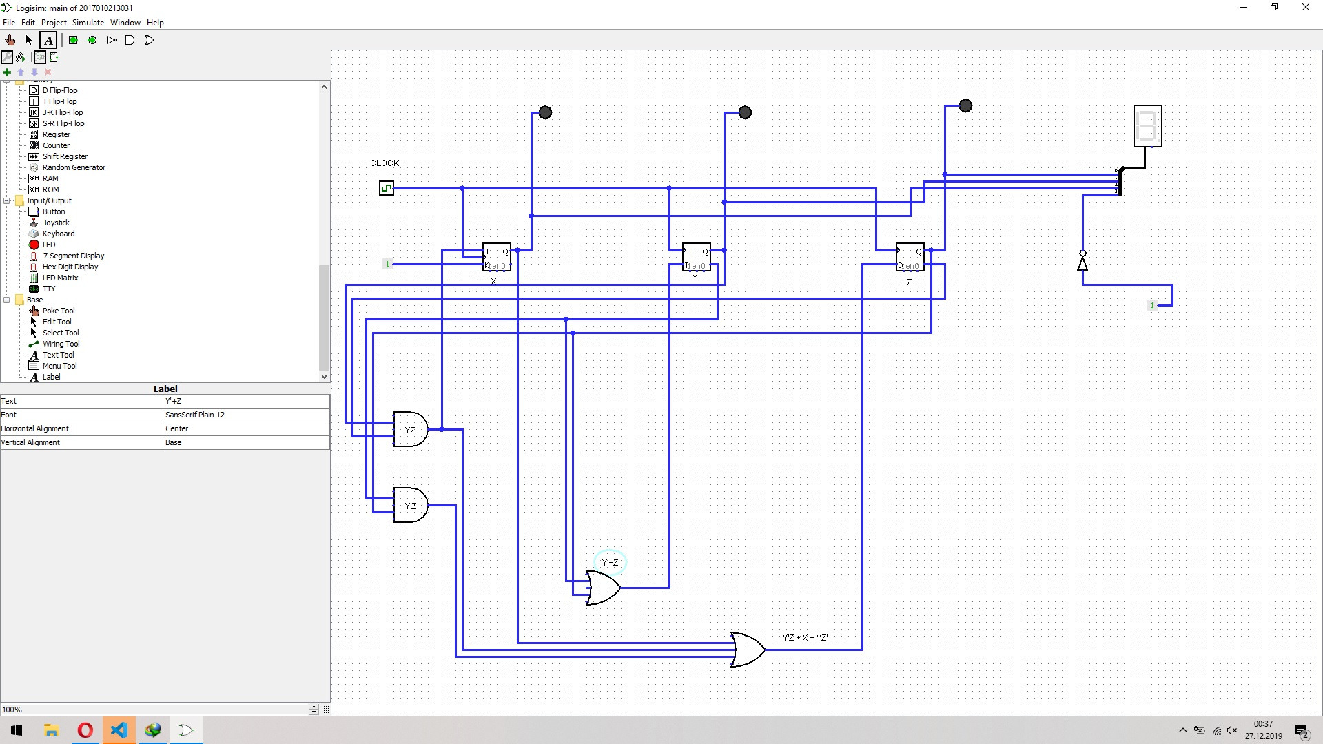
I understand you want to power-up with 1 (0b001) as the initial output. There is more than one way to do this, but probably the easiest for me to explain here is to configure your J-K flip-flop as a toggle type (TFF), just as you appear to do in your schematic. (I'll also include the DFF table, because it appears you are supposed to use one.)
Here's the table:
$$\begin{array}{c|c|c|c|c}
\text{State} & \text{Next} & \text{TFF}& \text{DFF}\\\\
{\begin{smallmatrix}\begin{array}{cccc}
Q_C & Q_B & \overline{Q_A}\\\\
0&0&1\\
0&1&1\\
0&0&0\\
0&1&0\\
1&1&1\\\\
1&0&0\\
1&0&1\\
1&1&0
\end{array}\end{smallmatrix}}
&
{\begin{smallmatrix}\begin{array}{cccc}
Q_C & Q_B & \overline{Q_A}\\\\
0&1&1\\
0&0&0\\
0&1&0\\
1&1&1\\
0&0&1\\\\
x&x&x\\
x&x&x\\
x&x&x
\end{array}\end{smallmatrix}}
&
{\begin{smallmatrix}\begin{array}{cccc}
T_C & T_B & T_A\\\\
0&1&0\\
0&1&1\\
0&1&0\\
1&0&1\\
1&1&0\\\\
x&x&x\\
x&x&x\\
x&x&x\\
\end{array}\end{smallmatrix}}
&
{\begin{smallmatrix}\begin{array}{cccc}
D_C & D_B & D_A\\\\
0&1&0\\
0&0&1\\
0&1&1\\
1&1&0\\
0&0&0\\\\
x&x&x\\
x&x&x\\
x&x&x\\
\end{array}\end{smallmatrix}}
\end{array}$$
The above table should be pretty easy to follow. The left column just shows the current state of your TFF outputs. The next column show you the next state that you want. The third column shows you which of the FF will need to be toggled (0 in the positions where there is no change in the bit value and 1 in the positions where there is a change.) The fourth column is really just a copy of the second column, except that the \$Q_\text{A}\$ isn't inverted.
There are then three TFF K-map tables drawn from the third column above:
$$\begin{array}{rl}
\begin{smallmatrix}\begin{array}{r|cccc}
T_C&\overline{Q_B}\:\overline{Q_A}&\overline{Q_B}\: Q_A&Q_B \:Q_A&Q_B \:\overline{Q_A}\\
\hline
\overline{Q_C}&0&0&1&0\\
Q_C&x&x&x&1
\end{array}\end{smallmatrix}
&
\begin{smallmatrix}\begin{array}{r|cccc}
T_B&\overline{Q_B}\:\overline{Q_A}&\overline{Q_B}\: Q_A&Q_B \:Q_A&Q_B \:\overline{Q_A}\\
\hline
\overline{Q_C}&1&1&0&1\\
Q_C&x&x&x&1
\end{array}\end{smallmatrix}\\\\
\begin{smallmatrix}\begin{array}{r|cccc}
T_A&\overline{Q_B}\:\overline{Q_A}&\overline{Q_B}\: Q_A&Q_B \:Q_A&Q_B \:\overline{Q_A}\\
\hline
\overline{Q_C}&0&0&1&1\\
Q_C&x&x&x&0
\end{array}\end{smallmatrix}
\end{array}$$
There are also three DFF K-map tables drawn from the last column above:
$$\begin{array}{rl}
\begin{smallmatrix}\begin{array}{r|cccc}
D_C&\overline{Q_B}\:\overline{Q_A}&\overline{Q_B}\: Q_A&Q_B \:Q_A&Q_B \:\overline{Q_A}\\
\hline
\overline{Q_C}&0&0&1&0\\
Q_C&x&x&x&0
\end{array}\end{smallmatrix}
&
\begin{smallmatrix}\begin{array}{r|cccc}
D_B&\overline{Q_B}\:\overline{Q_A}&\overline{Q_B}\: Q_A&Q_B \:Q_A&Q_B \:\overline{Q_A}\\
\hline
\overline{Q_C}&1&1&1&0\\
Q_C&x&x&x&0
\end{array}\end{smallmatrix}\\\\
\begin{smallmatrix}\begin{array}{r|cccc}
D_A&\overline{Q_B}\:\overline{Q_A}&\overline{Q_B}\: Q_A&Q_B \:Q_A&Q_B \:\overline{Q_A}\\
\hline
\overline{Q_C}&0&1&0&1\\
Q_C&x&x&x&0
\end{array}\end{smallmatrix}
\end{array}$$
Just skimming over the above tables, I'd use the DFF for the high order bit and use the JK and the TFF for the lower two order bits (doesn't matter which is which, since the JK is operated as a TFF, anyway.)
You'll need two AND gates and one NOT gate to get it done if you follow the above advice.
As it appears you have succeeded, here's the schematic I might try:


