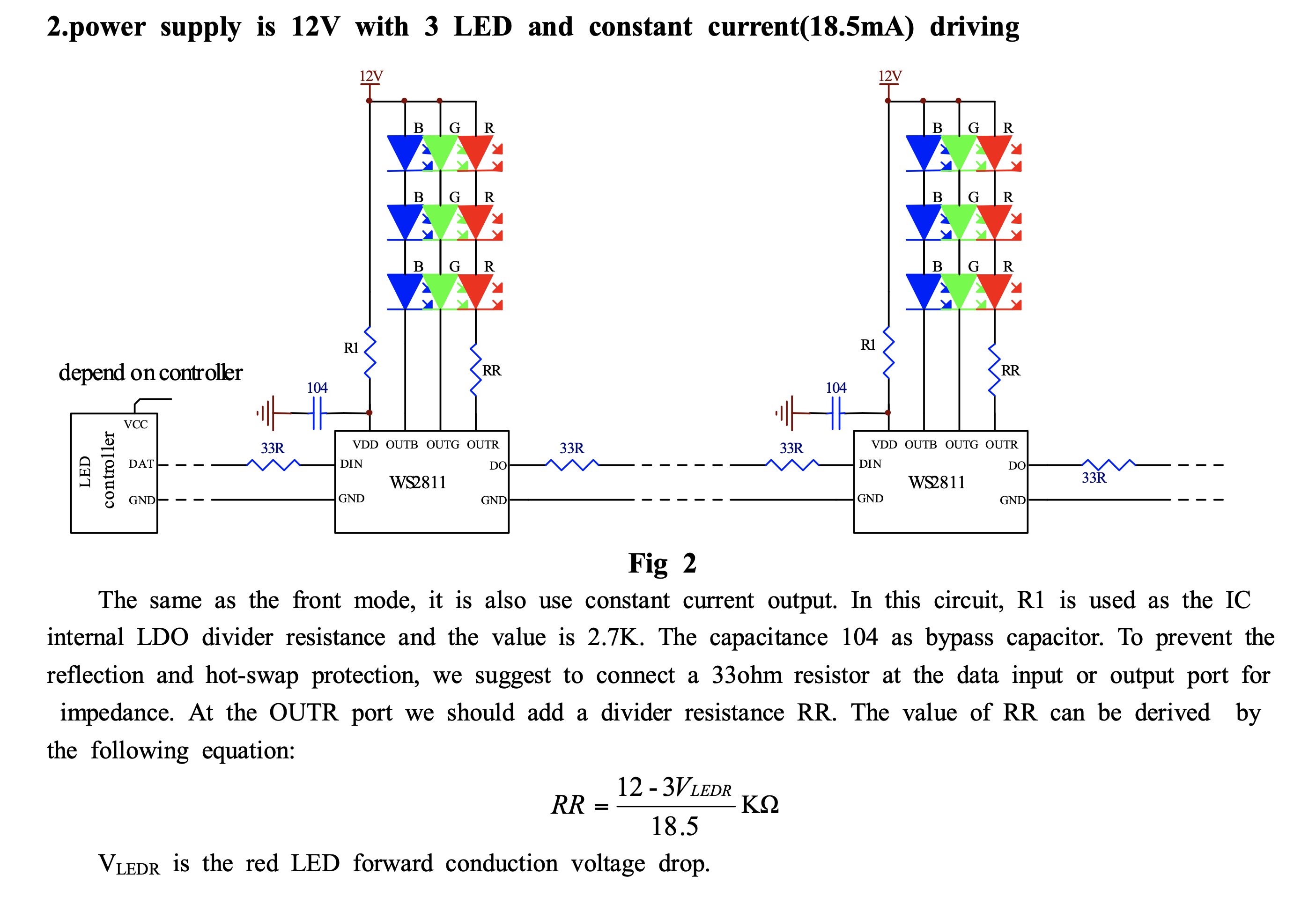
It doesn't really justify RR in the description, but I suspect it's there to limit the dissipation the IC has to handle. Green and blue LEDs have about 2-4V drop, so there would be about 6-12 volts drop across 3 of them. Red LEDs could be as low as 1.6V, so with 3 of them you might still have over 7V left from a supply of 12V. That's about 120-130mW that red driver has to dissipate.
You're correct that in this equation the 3 is for the 3 series red LEDs in the circuit. Whatever your configuration, you can use the same formula on each of the LED drive outputs to ensure the voltage on that output is low. If you have different devices/configurations which are similar in overall voltage drop, you can design for the highest drop version, it's not a critical parameter; if there's a difference of more than 4V total between lineups, you might want to consider additional resistors which can be switched in with jumpers.
Otherwise, you can find a PMOSFET to use in a current mirror that will dissipate the required power on its own, as shown in figure 9.1 here. Use the OUTR pin to drive Rbias on the left; Rbias should be (Vcc - Vgs(th) - 2V)/0.0185A (the 2V is margin to make sure we don't saturate the driver). Hook up the LED(s) on the right. If you get the PMOSFETS in a dual package (recommended) make sure it's able to dissipate 0.0185A * Vcc * 2 safely, and it should be good for any load.
 So, my first question is: The formula is RR=(12-3Vledrp)/18.5 K. Is this "3" multiplier mentioned there just because there are 3 LEDs on the schematic example? Or is it whole total voltage drop on all LEDs?
The second question:
I want to make it "universal" to be able to plug different LEDS, so I probably need some kind of constant current source controlled by the WS2811 "R" output. What could I use for that? As simple as it is possible?