0
\$\begingroup\$

I have been searching everywhere online on how to make this circuit. I found out I can make NAND gates using I2L and connect them together to make a T flip flop , but this is very impractical since I will end up using 48 transistors.

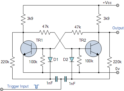
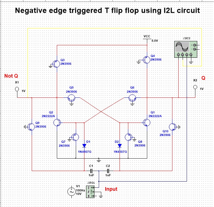
I found a circuit for a negative edge triggered T flip flop using Bistable multivibrators .

enter image description here

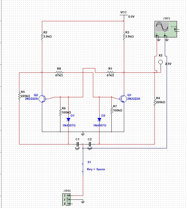
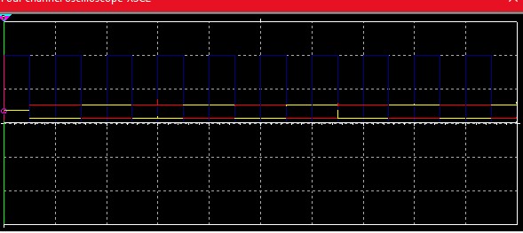
I connected the circuit in Multisim and tested it , and it gave me the correct output for a T flip flop.

enter image description here enter image description here

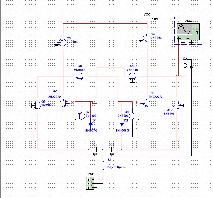
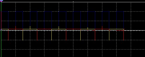
I figured that in order to make it I2L I have to replace every resistor in the circuit with a pnp bjt transistor ( 2n3906) as a current source and it should work, but it ended up giving me a really weird output.

enter image description here enter image description here

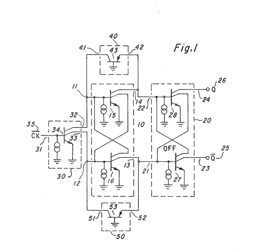
I also came across a different circuit from 1980 of a "Triggerable flip flop" using I2L , but it used multi-collector npn bjt transistors and I don't know to make these. (https://patents.google.com/patent/EP0032154A1/en)

enter image description here

Please help me either fix the circuit I made so it works and tell me how to make a multi-collector npn bjt.

Thank you

\$\endgroup\$
3
  • \$\begingroup\$ For most purposes, a multi-collector transistor is equivalent to two (or more) transistors with their bases and emitters connected in parallel. The transistors need to be well-matched for best results. \$\endgroup\$
    – Dave Tweed
    Commented May 5, 2021 at 0:21
  • \$\begingroup\$ What’s the fascination with 50 yr old technology replaced the following year by TTL , see p3 ti.com/lit/ds/sdls119/… \$\endgroup\$
    – D.A.S.
    Commented May 5, 2021 at 0:36
  • \$\begingroup\$ Its a project I need to finish, I really don't care about or like the technology , for some reason the professor decided to assign a project to me where I have to make a simple component using an obsolete technology. \$\endgroup\$
    – DeadSlayer
    Commented May 5, 2021 at 0:52

2 Answers 2

0
\$\begingroup\$

You cannot connect the emitter of a PNP transistor to +5V and the base to ground. That will burn out the transistor. Instead, you must include a resistor, either between base and ground, or between the emitter and +5V. I have only seen the later today, when researching I2L logic. (Actually it seems pretty interesting).

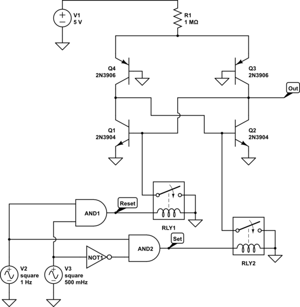
Although I don't have a circuit for a edge-triggered D-Flip-Flop, I do have an I2L circuit for an SR-latch. That should give you implementation ideas.

schematic

simulate this circuit – Schematic created using CircuitLab

[That part of the circuit that includes the relays and everything "below" the relays is there only for testing purposes. It is not part of the I2L SR-latch.]

Notice that there is a resistor between Vcc and the PNP transistor emitters. Changing that resistor will change the current consumed by the SR-latch.

The output of the circuit is:

enter image description here

enter image description here

Hope this get's you on your way!

\$\endgroup\$
0
\$\begingroup\$

I was able to fix the circuit I posted above by simply changing the value of the capacitors from 1uf to 1nf

enter image description here

enter image description here

Though if I added any value of resistance ( to the VCC) , it completely destroys the output.

enter image description here

What Can I do about this ?

\$\endgroup\$
3
  • \$\begingroup\$ Maybe I can decrease the vcc ? \$\endgroup\$
    – DeadSlayer
    Commented May 5, 2021 at 8:51
  • \$\begingroup\$ Per my answer, you cannot connect the emitter of a PNP transistor to +5V and the base to ground. That will burn out the transistor. I am referring specifically to Q3 and Q4 in your schematic. Your simulator may not complain, real transistors will. Check the base current in those transistors with your simulator. \$\endgroup\$ Commented May 5, 2021 at 11:12
  • \$\begingroup\$ 404 mA, which will probably burn it \$\endgroup\$
    – DeadSlayer
    Commented May 5, 2021 at 11:35

Your Answer

By clicking “Post Your Answer”, you agree to our terms of service and acknowledge you have read our privacy policy.

Not the answer you're looking for? Browse other questions tagged or ask your own question.