3
\$\begingroup\$

I am reading Art of Electronics book. There is a question:

Here is an interesting problem: What load resistance will result in maximum power being transfered to the load for a given source resistance? (The terms source resistance, internal resistance, and Thevenin equivalent resistance all mean the same thing.) It is easy to see that either R_load = 0 or R_load = \$\infty\$ results in zero power transferred, because R_load = 0 means that V_load = 0."

I do not understand why R_load = 0 leads to V_load = 0.

  • Why does V_load depends on R_load?
  • What exactly is meant by power transfer?

I think I understand energy transfer, but not the power.

I think I understand that when R_load = 0 all energy is dissipated by the resistor and when R_load = \$\infty\$ we have not current so there is no energy transfer.

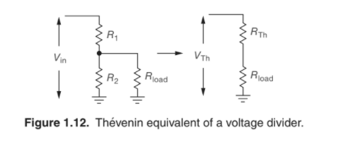
Here is a relevant (or maybe not) illustration from the book:

illustration

\$\endgroup\$
2
  • 5
    \$\begingroup\$ Not so relevant illustration. \$\endgroup\$
    – JRE
    Commented Sep 23, 2021 at 14:51
  • 9
    \$\begingroup\$ I do not understand why R_load = 0 leads to V_load = 0. Explain to me how you could get a non-zero \$V_{load}\$ across a load that has a resistance \$R_{load}\$ = 0 Ohms (zero Ohms, a short). I suggest to look at Ohm's law. \$\endgroup\$ Commented Sep 23, 2021 at 15:00

5 Answers 5

8
\$\begingroup\$

If you under stand energy transfer, then power transfer is the same thing. Energy is \$E=P*t\$ where \$P\$ is in watts and \$t\$ is in seconds. Power transfer is just instantaneous energy transfer.

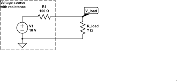
Take a simple circuit:

schematic

simulate this circuit – Schematic created using CircuitLab

Now recall Ohm's law and the power law: $$ V = IR $$ $$ P = VI $$

If \$R\__{load} = 0\$, then it doesn't matter what \$I\$ is. \$V\__{load}\$ will always be 0, as will power dissipated in \$R\__{load}\$.

If \$R\__{load}\$ is open, then \$I\$ will be zero, and so will the power dissipated in \$R\__{load}\$.

Between those extremes, the power dissipated in \$R\__{load}\$ will vary. From low values for \$R\__{load}\$, the power dissipated in \$R\__{load}\$ will increase as the resistance increases. At some point, the power will reach a maximum, then decline as \$R\__{load}\$ continues to increase.

Art of Electronics wants you to consider how the electronics play together, then look at what the math says.

An interesting exercise would be to set up an equation using Ohm's law and the power law to calculate the dissipated power in \$R\__{load}\$ from \$V_1\$, \$R_1\$, and \$R\__{load}\$ then plop it into a spreadsheet and plot the curve to see how they are all related.

\$\endgroup\$
13
\$\begingroup\$

It may be worth slogging through the exact math to illustrate what's happening here. Assuming a source resistor \$R_S\$ and a load resistor \$R_L\$ the current through both resistors will simply be

$$I = V\frac{1}{R_S+R_L}$$

We can calculate the voltage over the load as a simple voltage divider $$V_L = V\frac{R_L}{R_S+R_L}$$

The power over the load becomes

$$P = I \cdot V_L= V^2\frac{R_L}{(R_S+R_L)^2}$$

If \$R_L\$ is very small the power becomes zero because the numerator becomes 0. If \$R_L\$ is very large the power also becomes zero since the \$R_L^2\$ term in the denominator dominates. In other words if \$R_L\$ is small the load voltage becomes zero and if \$R_L\$ is large, the load current becomes zero. In either case the product of the two becomes zero too.

Let's take a look at a graph for a source of 1 Volt/1 Ohm:
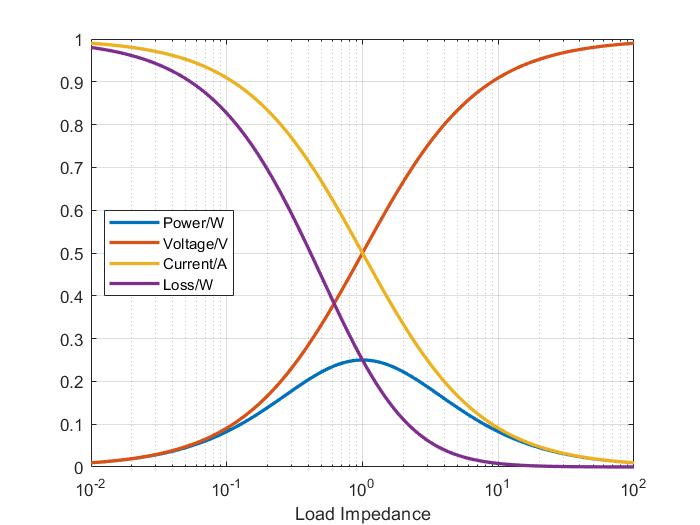
enter image description here

The graph show power, voltage and current of the load as well as the "loss" which is the power consumed inside the source. Even though the source can deliver a maximum of 1 Watt, the max we can get into the load is 0.25 Watts. At this point the power in the source and the load is the same, so the efficiency is 50%.

To maximize the power, we need maximized this function, i.e. solve for

$$\frac{\partial P}{\partial R_L} = 0$$

Unfortunately that's bit of a slog. Using the quotient rule, we get

$$0 = \frac{\partial P}{\partial R_L} = V^2\frac{(R_S+R_L)^2-2R_L(R_S+R_L)}{(R_S+R_L)^4} $$

We can dump the constant multipliers and get:

$$0 = (R_S+R_L)^2-2R_L(R_S+R_L) = R_S^2+2R_SR_L+R_L^2-2R_LR_S-2R_L^2 = R_S^2-R_L^2$$

Technically this has two solutions

$$R_L = \pm R_S$$

but if only allow positive resistances, the only solution is

$$R_L = R_S$$

If we would allow for complex impedances, we would get \$Z_L = Z_S^*\$, i.e. load and source impedance have the same magnitude but opposite phases. We leave this derivation for another day :-)

\$\endgroup\$
4
\$\begingroup\$

The load current

\$I_{LOAD} = V_{TH}/(R_{TH} + R_{LOAD})\$.

Note that when \$R_{LOAD}\$= 0 the current is just \$I_{LOAD}= V_{TH}/R_{TH}\$

(in particular, note that it is finite for \$R_{TH} \gt 0\$ ).

The power in the load is \$R_{LOAD}\cdot I_{LOAD}^2\$, so when \$I_{LOAD}\$=0 or \$R_{LOAD}\$=0 the power is zero.

Also note that the load voltage will vary from \$V_{TH}\$ for \$R_{LOAD}\$ = \$\infty\$ to 0 for \$R_{LOAD}\$ = 0 since it is equal to \$I_{LOAD}\cdot R_{LOAD}\$


Power is just energy transfer per unit time, so if you understand energy you will understand power.

Typically to find the maximum power transfer condition you write the equation for load power as a function of load resistance and then differentiate wrt the load resistance and equate that to zero to find the maxima (or it could be a minima).

As AoE will tell you, that value is just \$R_{LOAD}= R_{TH}\$

\$\endgroup\$
3
\$\begingroup\$

Let's look at the right side of the image you posted. It shows a finite fixed voltage, \$V_{th}\$ applied across two resistors in series, \$R_{th}\$ and \$R_{load}\$. (I think the left half and the transformation from the left to the right side is irrelevant here, but will become useful in the future as you analyze more complex source circuits)

Because the resistors are in series, they must have the same current flowing through them (call it \$I\$), and the voltage across them must sum to \$V_{th}\$. This current is finite because Rth is nonzero, and we apply Ohm's Law (V=IR) to the load resistor: \$V_{R_{load}} = IR_{load}\$. Consequently, if Rload is 0 then the voltage across it is zero, no matter what finite value the current takes. Without a voltage across the load, whatever current passes through it can do not work and hence no power or energy are provided.

In the infinite resistance case, no current can flow because the input voltage is finite. Without current, there is no energy or power delivered to the load.

\$\endgroup\$
1
  • \$\begingroup\$ Thank you, this is great answer! Indeed is makes much sense for the right side now. I guess this only applies to the right side, since for the left side we will still have voltage difference when $R_load = 0$ \$\endgroup\$ Commented Sep 23, 2021 at 15:04
2
\$\begingroup\$

The maximum power transfer occurs when the load (Rl) is equal to that from the source (Rs). however, the efficiency is affected.

Please read the wiki from the maximum power transfer theorem.

This is a typical case scenario when functions maximization is taught at initial calculus courses. The math that gives you this result can be obtained in a few steps (as described in the wiki).

\$\endgroup\$

Your Answer

By clicking “Post Your Answer”, you agree to our terms of service and acknowledge you have read our privacy policy.

Not the answer you're looking for? Browse other questions tagged or ask your own question.