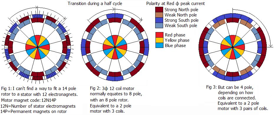
Most drone or quad copter motors have a 14 pole rotor instead of an 8 pole one around a 12 coil 3 phase stator as in top picture. The only reason I can imagine for this is to reduce torque ripple, but efficiency would be seriously compromised. If there is somebody out there involved with the design of these motors with the magnet code 12N14P, could you please tell me how they work, and why do they have that design. It doesn't make sense.😬 You can use the fill tool in Paint to modify my diagram and use in your explanation.
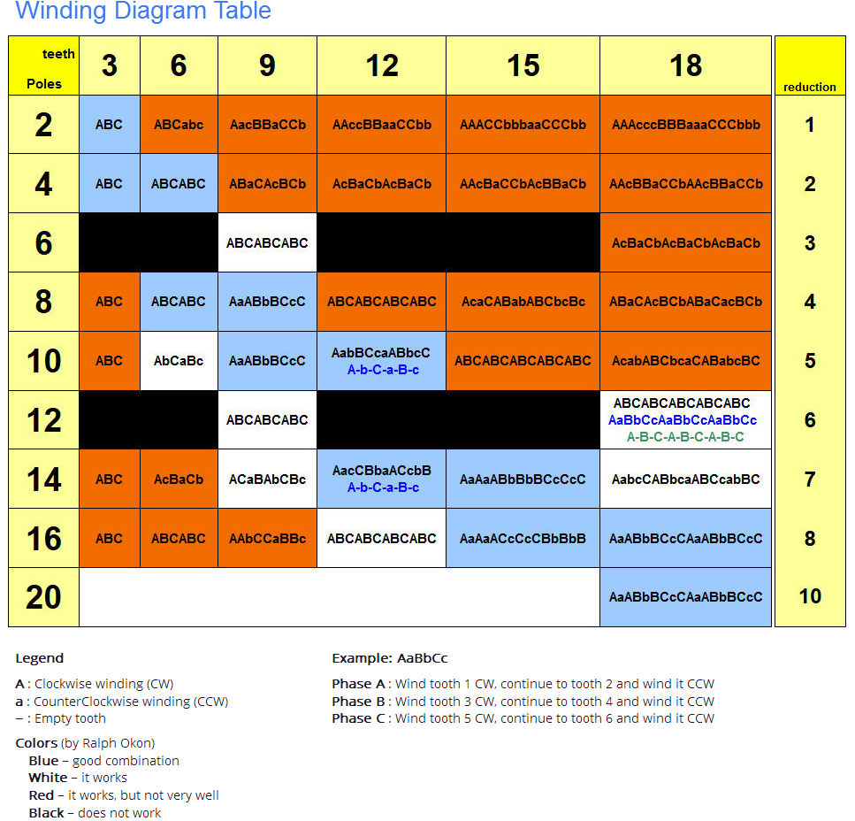
Edit: I have added a winding table I found on the net. I haven't been able to find out why they have black, blue & green letters, and the blue in the 12 teeth/14 pole, and the black & green in the 18 teeth/12 pole don't match the number of teeth. In the 18 tooth one, the 9 green letters, and the 6 blue in the 12 tooth could be every 2nd tooth, but the 15 black in the 18 tooth?......What the.......?
-
\$\begingroup\$ Read aerodesign.de/peter/2001/LRK350/index_eng.html and eggelectricunicycle.bitbucket.io/… \$\endgroup\$– user16324Commented Nov 7, 2021 at 18:16
-
\$\begingroup\$ More poles means more electrical/commutation cycles per mechanical rotation which is essentially electromagnetic gearing to try and get away without a gearbox. Slower rotation but more torque. \$\endgroup\$– DKNguyenCommented Nov 8, 2021 at 3:24
-
\$\begingroup\$ @user_1818839 Thanks. Those sites were very informative (along with a German to English translation site). I get the general idea. I copied the animation and still frame so I can fill in all the phases and get the whole picture. I need to think about it for a while, but that was a great start. I have never seen that method of getting so much speed reduction for the number of poles. \$\endgroup\$– Peter R. McMahonCommented Nov 8, 2021 at 4:15
-
\$\begingroup\$ @user_1818839 I added a winding table I found, to my question. It has multiple combinations in some boxes as explained in the edit, but no explanation as to why. Could you help me with that please? \$\endgroup\$– Peter R. McMahonCommented Nov 21, 2021 at 15:16
1 Answer
If there is somebody out there involved with the design of these motors with the magnet code 12N14P, could you please tell me how they work, and why do they have that design.
The basic scheme for a 3 phase motor is 2 poles and 3 teeth with 1 phase per tooth, which produces 1 revolution per 6 step commutation cycle. Multiples of this can be applied to make the motor run slower and produce more torque. So 4 poles and 6 teeth is electrically the same as 2 poles and 3 teeth, but halves the mechanical rotation angle per commutation cycle.
When you have more teeth it may be possible to use a different winding pattern, with the windings skipping teeth or spread over several teeth.
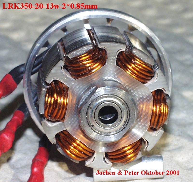
LRK (named after Lucas, Retzbach and Küfuss who pioneered this scheme in model aircraft motors) skips every other tooth. The 'unpopulated' tooth acts like the other arm of a horseshoe magnet, producing the opposite magnetic pole to the wound tooth. Here is an example:-
This scheme is easier to wind because there are half as many teeth to wind and the wire can be packed in without interference from the neighboring winding. However it may be less efficient magnetically because it relies totally on the 'spare' tooth to conduct the magnetic field back up to the rotor.
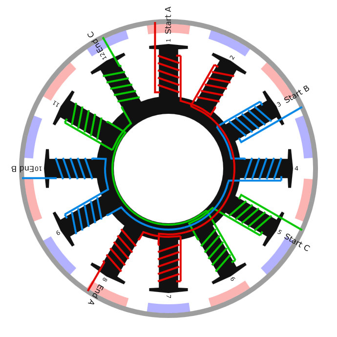
The most popular scheme used today is dLRK, which fills adjacent teeth with the same winding like this:-
Note that the winding direction of each tooth in a pair is opposite, equivalent to a horseshoe magnet with a winding on either side.
It is also possible to wind adjacent teeth in the same direction forming a pole that covers several teeth. This is used to reduce the effective number of teeth in a stator, which is useful if you have a stator with a large number of teeth but want a faster running motor.
Compared to a geared motor, having a large number of teeth may be a bit less efficient electrically due to more wasted space between the smaller teeth. However it saves the weight and losses of a gearbox, is cheaper to manufacture and easier to maintain, and produces a 'squat' form factor which suits some applications better.
the blue in the 12 teeth/14 pole, and the ... green in the 18 teeth/12 pole don't match the number of teeth.
The dashes represent teeth that do not have windings on them. The last dash has been omitted, but is implied since in these schemes every winding has a gap after it.
but the 15 black in the 18 tooth......What the......?
This is another omission. There should be another 3 letters continuing the ABC sequence to make one winding per tooth. This scheme is electrically identical to 2 poles and 3 teeth with ABC winding.
-
\$\begingroup\$ I'd say they probably did bungle it with the 15 letters, like they did with the sequence of the black letters in the 12 tooth/14 pole. It's hard enough to understand these things without them making mistakes.😬 \$\endgroup\$ Commented Nov 23, 2021 at 5:07
-
\$\begingroup\$ I guess they forgot to put the extra ABC in. They also showed the 12 tooth/14 pole black letters in a CCW sequence. I understand it now. Thanks for your help! \$\endgroup\$ Commented Dec 7, 2021 at 13:23
-
\$\begingroup\$ @ Bruce Abbott I stand corrected on the AacCBbaACcbB being CCW. Now I understand it with a bit of help from you, and the sites suggested by user_1818839, when I followed the sequence, I found it is actually CW. \$\endgroup\$ Commented Dec 24, 2021 at 8:19

