7
\$\begingroup\$

I am trying to find a fault on a multilayer board currently. I use mostly my multimeter in buzzer mode and came across such a situation.

When I measured a 1 kΩ resistor in buzzer mode it didn't beep as expected and gave the resistance as 900 Ω. When I switched to resistance measuring mode I read 1 kΩ consistently.

But the weirdness came into scene when I tried to determine where the base resistor of an NPN is being driven from. I began my search by contacting one of the probes to the one end of the resistor in buzzer mode. Then I visited all the vias and devices over the board for the other end. I couldn't locate it; possibly an open circuit. But I measured around 500 Ω at some parts of the board. When I checked those parts in resistance measuring mode I read 100 kΩ.

So if I summarize:

When I measure a resistor of 1 kΩ

  1. in buzzer mode I read 900 Ω
  2. in resistance measuring mode 1 kΩ.

When I try to locate a route with a floating end (possibly an open circuit)

  1. in buzzer mode I read 500 Ω
  2. in resistance mode I read 100 kΩ

What could be the possible reason for these conflicting measurements?

\$\endgroup\$
3
  • 7
    \$\begingroup\$ It is useful to repeat the measurement with reversed probes to see if there is a non-linear device (diode, PN junction...) \$\endgroup\$ Commented Jan 4, 2023 at 12:19
  • 8
    \$\begingroup\$ You say that you are measuring a single resistor, but imply that it is still fully attached to the rest of the circuit? If so, you are measuring the entire circuit... \$\endgroup\$
    – MikeB
    Commented Jan 4, 2023 at 17:13
  • \$\begingroup\$ Per Circuit fanatacist above, what happens when you reverse the probes and apply a test current of opposite polarity? If the results are different, that should tell you that some diode action is going on. I highly recommend the WP-34s calculator (which is no longer available, but can be had as a free iPhone download. It has the Lambert W function, which you can use to solve diode equation problems without iteration. You don't need impossible high tech solutions like SPICE. \$\endgroup\$ Commented Jan 5, 2023 at 23:13

4 Answers 4

14
\$\begingroup\$

Modern DMMs measure resistance by injecting a small current through the probes and measuring the voltage drop that develops across the probe terminals (most sophisticated bench DMMs can also perform more accurate 4-wire measurements, a.k.a. Kelvin measurements, where the current is injected by a pair of probes which is different from the probes used for measuring the voltage drop).

In other words, the ohm function makes the DMM behave like a current source with a constant current value. This is the so called test current, which is often specified in the DMM's manual.

To allow measuring resistors in-circuit (which is a nice feature to have in a DMM) the test current is often quite small, so that the DMM's current source circuitry can provide it by generating a voltage that is small enough to avoid turning on semiconductor devices junctions.

For example, if an ohm function range uses a 1μA test current, then it can be used to measure resistors with a value of about 0.5V / 1μA = 500kΩ without turning on silicon PN junctions, which turn on at about 0.6V (you would need still smaller currents to measure the same resistance without turning on Schottky or Germanium diodes).

Such a tiny test current, however, when injected in a low resistance path will generate a really tiny voltage, which may be difficult to measure by the internal DMM circuitry.

E.g., the same 1μA current above will generate a scant 10μV voltage drop across a 10Ω resistor, voltage which is down in the noise in most situations and requires quite a sophisticated (and expensive) measurement circuitry.

Therefore, DMMs circuitry increase the test current when using ohm's ranges designed to measure low resistance values.

Since continuity testing is just meant to detect such low resistance values, (assuming the continuity function uses the same circuit used for resistance measurements) the test current is usually quite substantial (1mA is not uncommon).

Therefore, when the probes are applied to the circuit under test, if a high resistance path lies across the terminals, the current source is forced to generate a higher voltage in order to pump the test current into the circuit. This will turn on PN junctions, giving false readings for the resistance value.

For example, with a 1mA test current it is sufficient to have 500Ω of resistance across the probe terminals to generate a 500mV drop, which is enough to bring silicon diodes in conduction (and more so Schottky or germanium diodes). This will clamp the voltage to that value, making the DMM show you a 500mV/1mA = 500Ω value on the display.

If you want to check if this is really your case, try and measure with another DMM the test current put out by your original DMM on its continuity function. If it measures about 1mA you have a high chance that during the continuity measurement you turned on some semiconductor junction.

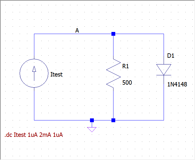
To show you what happens in a more practical way, here is a quick and dirty LTspice simulation of the following circuit, modeling the situation of a current source supplying current to a resistor in parallel with a diode:
enter image description here

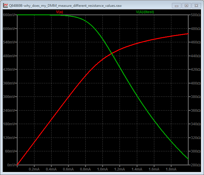
The following are the results of a DC-sweep simulation with various test current values on the horizontal axis. The red curve is V(a), which is the voltage between the probes (what the DMM actually measures), and the green curve is the ratio between V(a) and the test current (that is, what the DMM actually displays).
enter image description here

As you can see, when the current is low enough, the DMM displays the correct value of 500Ω, i.e. that of the resistor R1. Once the current reaches about 0.7mA D1 begins to turn on, the voltage at A is clamped to about 0.6V and the displayed value decreases.

Now, since you said you measured 100kΩ with the resistance function, I was curious to reproduce it in the simulation, so I changed R1 to 100k. Here are the results:
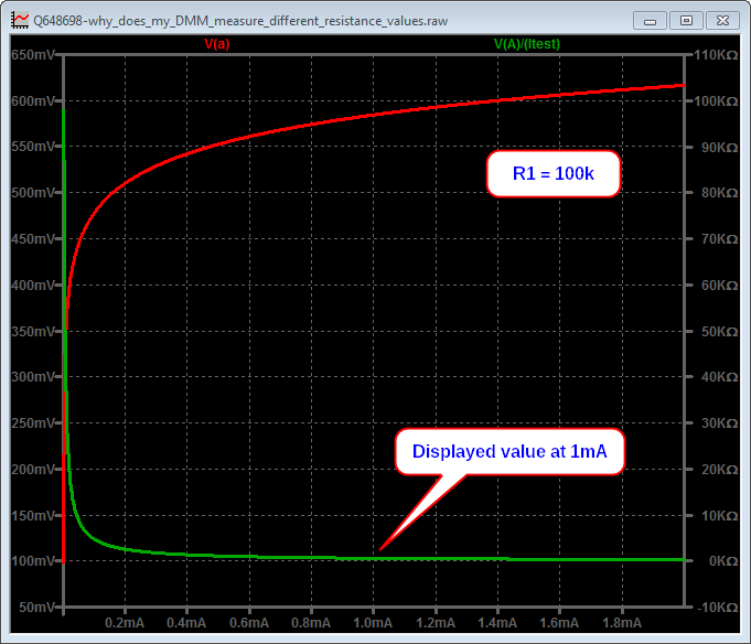
enter image description here

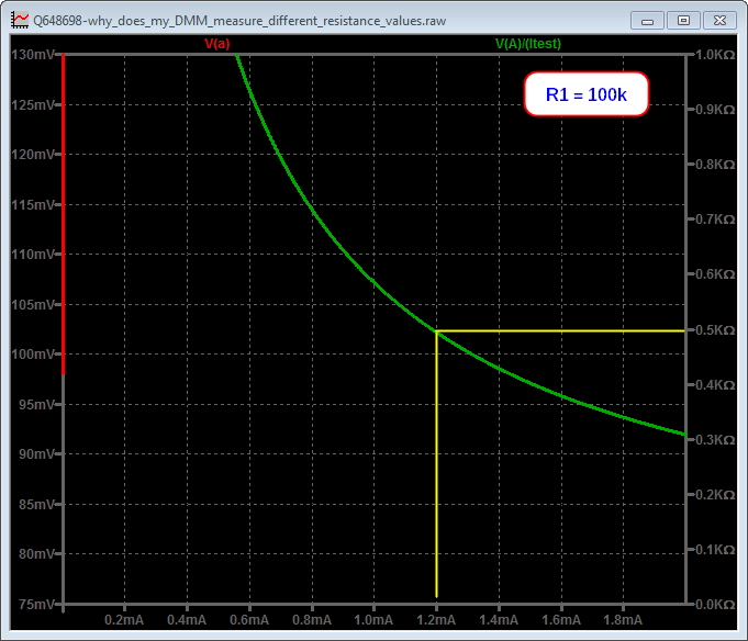
which is pretty unreadable, but zooming in gives this picture:
enter image description here

I have added the yellow lines, which highlight that you would get a reading of 500Ω with a test current of about 1.2mA, which may be coherent with your situation.

I'd really like to hear you back telling us what test current value your DMM actually generates, as a definitive confirmation of my hypothesis.

\$\endgroup\$
4
  • 1
    \$\begingroup\$ Huh, I had no idea that (some) DMMs were designed with the intention of measuring resistors in-circuit. \$\endgroup\$ Commented Jan 4, 2023 at 19:21
  • \$\begingroup\$ @user253751 Many years ago there were also some DMMs with a "low-ohm" option for ohm ranges. It traded low current with accuracy. You got a lower test current (allowing in-circuit measurement of resistances) but worse accuracy. \$\endgroup\$ Commented Jan 4, 2023 at 19:27
  • 2
    \$\begingroup\$ @user253751 Now there is no need for that switch, since modern DMM chipsets are quite capable of handling very low current measurements anyway. \$\endgroup\$ Commented Jan 4, 2023 at 19:28
  • \$\begingroup\$ Yes, I have an old DMM with a "low power" ohms setting, designed to read voltages of 200 mV maximum as opposed to 2V full scale for 3.5 digits. \$\endgroup\$
    – PStechPaul
    Commented Jan 5, 2023 at 3:50
10
\$\begingroup\$

When there are nonlinear elements such as the Base-Emitter junction of a transistor in the circuit, the apparent resistance depends a lot on the measuring circuit and how much voltage it applies to the circuit. For example, on a typical multimeter diode/continuity (beeper) range the multimeter applies enough voltage that a silicon diode will conduct. Depending on the meter, the number you see may not be resistance, but rather the forward voltage in mV with ~1mA current.

You may also find that the resistance measurement varies greatly with the multimeter range if there are nonlinear elements. In-circuit measurements are prone to misinterpretation for this, and other, reasons.

You can, however, be sure that if the measurement is many ohms (no matter the range) there is no continuous copper trace between the points.

\$\endgroup\$
1
\$\begingroup\$

The multimeters I know don't display ohms in "buzzer mode" but millivolts of voltage drop. That's for measuring diodes (and transistors). A silicon diode in pass direction will show something like 650, Schottky diodes will be smaller. Measuring 500 millivolts is perfectly consistent with measuring 100kohms depending on the test current/voltage that an ohms measurement will take: it may be lower than the drop voltage of a nonlinear device.

Check out some silicon diode in isolation: if that delivers a reading between 600 and 700 in pass direction, that would be a strong clue that this is the case here.

\$\endgroup\$
1
  • \$\begingroup\$ Right. Very often continuity mode is diode mode with the addition of a beep when the voltage drop is low enough. Some multimeters don't even have a separate mode; they beep in diode mode and continuity mode and diode more are both marked on a single switch position (and there is no mode switch to change between them). \$\endgroup\$
    – cjs
    Commented Jan 5, 2023 at 8:15
0
\$\begingroup\$

In-circuit component measurement tests are often problematic. For example, you may see the value change rapidly and then slowly stabilise, this is very common when larger capacitances are influencing the voltages at your probes.Continuity check on most volt meters is generally very rough, don't rely on the reported resistance values when your volt meter is in continuity mode. While you may place probes across (for example) a resistor, the resistor is likely part of a bigger network on the circuit board and the ends may interact with IC terminals, capacitors, transistors and switches, other devices. You might have to un-solder an end of a component to test it properly. not only the above issues, but in some more sensitive circuits, the probes, leads and internal circuitry of the voltmeter may interact and alter the result. Metering low values of current is another common issue, you may be a bit lower in circuit current than the low point of a higher volt meter Amps range but when you reduce the voltage range you are probably switching probes to a lower current set of connections on the meter and this circuit is typically more sensitive at the expense of having a higher resistance internal shunt it can measure with. This low ohm shunt resistor is in circuit with your test circuit and will reduce the reading you would have if the shunt was instead shorted.

\$\endgroup\$

Your Answer

By clicking “Post Your Answer”, you agree to our terms of service and acknowledge you have read our privacy policy.

Not the answer you're looking for? Browse other questions tagged or ask your own question.