3
\$\begingroup\$

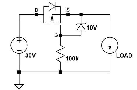
A typical PFET reverse polarity detection circuit looks like this

enter image description here

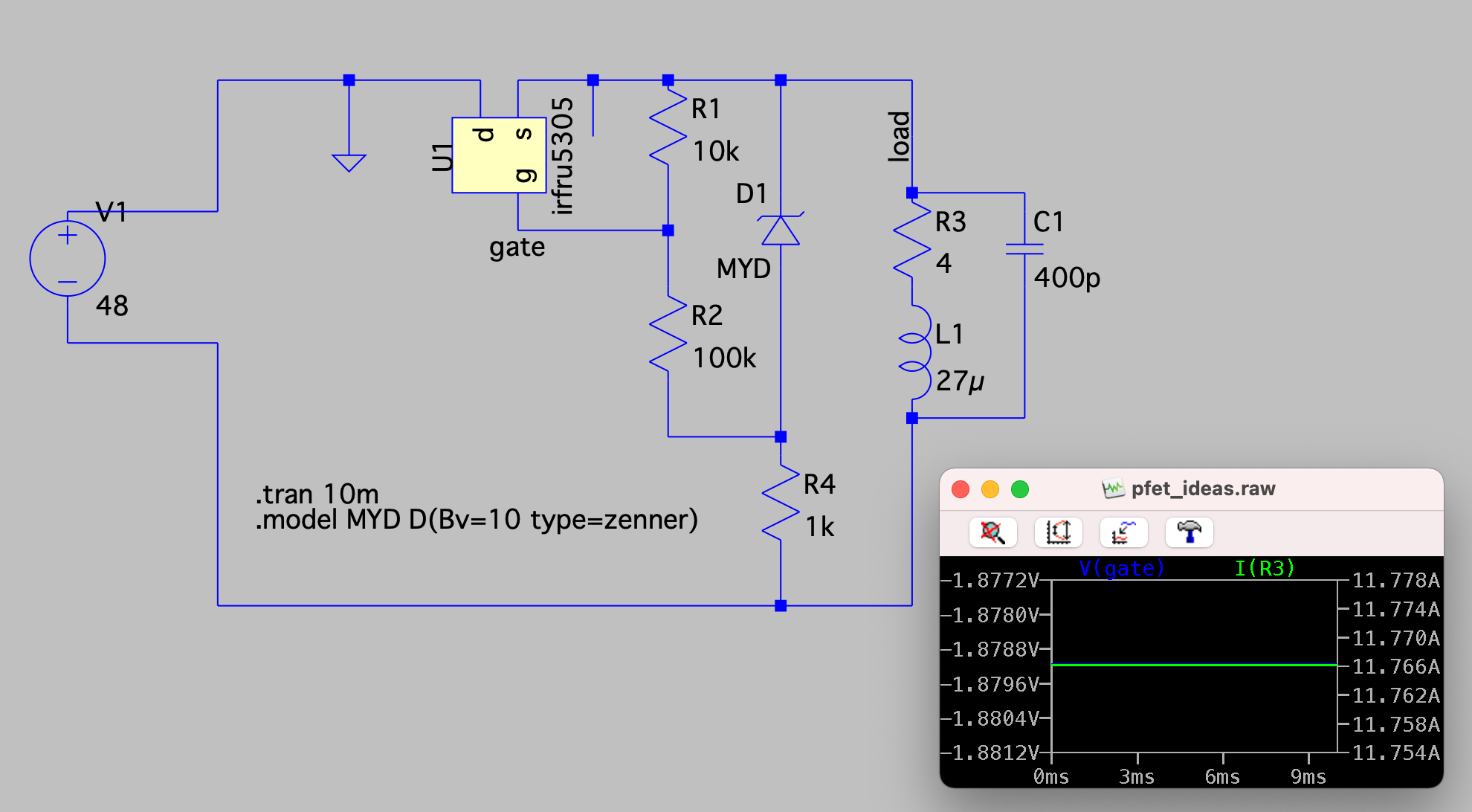
I was wondering if it is possible to use that same PFET to choke some power off to the load by adding a voltage divider using something like the following . .

enter image description here

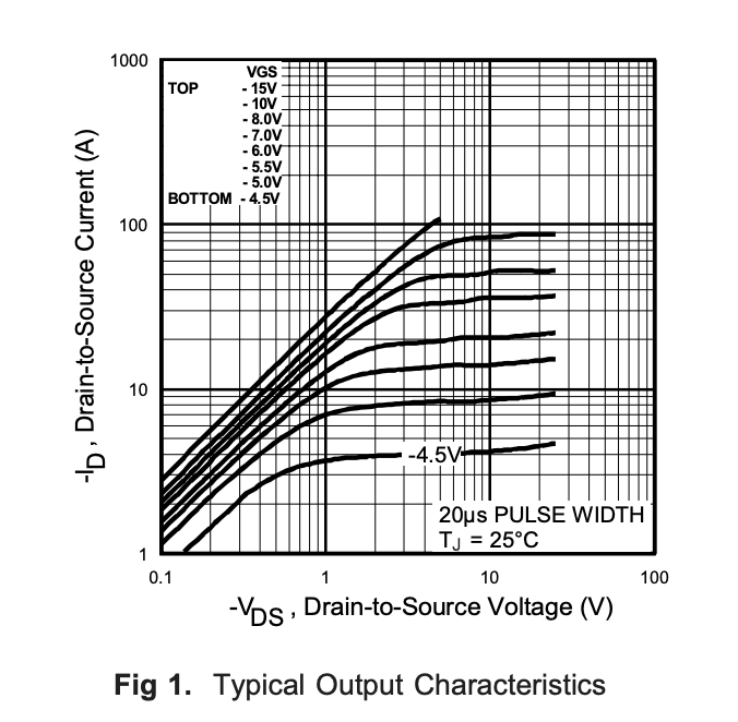
The simulation output shows 11.76A to load, even though the data sheet for the component is shows the following, so with a Vds of 48V I would expect to see some reduction in current in the LTSpice simulation with a VGs of less than 4.5V.

Few options:

  • The spice simulation is not working correctly (used the spice model from vendor here)
  • The spice sim is accurate and I'm not understanding something.
  • This circuit is a fundamentally bad idea for other reasons

enter image description here

\$\endgroup\$
1
  • 3
    \$\begingroup\$ Notice the thing in your first drawing that looks like a diode with the anode on "D" and the cathode on "S"? It's effectively a real diode, so (48 V-0.8 V)/4 ohm = 11.8 A \$\endgroup\$
    – John D
    Commented Aug 29, 2023 at 17:46

2 Answers 2

5
\$\begingroup\$

I was wondering if it is possible to use that same PFET to choke some power off to the load by adding a voltage divider using something like the following [...]

Yes and no. The idea is sound, except the pesky body diode will start to conduct if the output is more than say 0.7V below the input. So you could drop up to 0.7V, at which point the channel conductance gets bypassed by the body diode.

So, to do what you want requires two pass devices, connected back-to-back, so that their body diodes cannot conduct at the same time. The gates can be connected together and controlled from a single voltage source.

What you're getting is a reverse-voltage protected low-dropout voltage regulator. You can also buy them in single-chip form, but of course the selection of parameters is not as wide as what you could design from discrete parts and op-amps.

\$\endgroup\$
2
\$\begingroup\$

To answer your question - yes. With an independent voltage reference and a feedback amplifier, usually an opamp, you can turn the overall circuit into either a regulated constant-voltage output, or a regulated constant-current output.

What you are doing, sorta kinda, is dangle-biasing the FET to a specific point in its conduction curves. That is a very iffy thing to do. This is a very soft parameter, and varies with temperature. If I understand your description, I think you are biasing the FET to behave as either a constant resistance or as a constant-current diode, depending on where you are on the curves.

A p-channel FET is a common element in a low dropout (LDO) voltage regulator. A lowcost opamp in a conventional feedback regulator circuit will work much more predictably. The innergoogle is awash with schematic examples.

\$\endgroup\$
1
  • 4
    \$\begingroup\$ Except the PFET in the OP's circuit is in the right direction for reverse-polarity protection but not for a pass element. The body diode will always conduct so you'll only be able to modulate the load current by dropping maybe 0.8 V. \$\endgroup\$
    – John D
    Commented Aug 29, 2023 at 18:11

Your Answer

By clicking “Post Your Answer”, you agree to our terms of service and acknowledge you have read our privacy policy.

Not the answer you're looking for? Browse other questions tagged or ask your own question.