0
\$\begingroup\$

This is a problem solving for the voltage across a capacitor with initial conditions. After finding initial conditions and transforming into s-domain, the circuit looks like this: image of circuit
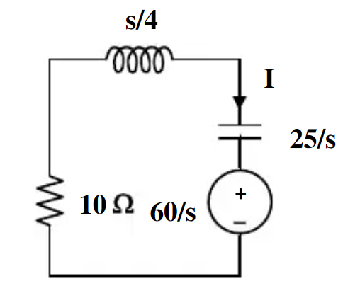
So, the voltage we are solving for includes both the capacitor and the voltage source in s-domain. $$ V(s) = I\frac{25}{s}+\frac{60}{s} $$ I can get the correct answer for this problem using the equation below from mesh analysis and the equation above: $$ I(\frac{25}{s}+\frac{s}{4}+10)=-\frac{60}{s} $$ However, initially, I thought voltage division might be easier. I thought the node between the inductor and the capacitor would be the same as V(s), just negative as we would have to assume the current is going in the opposite direction of \$I\$ for the voltage division. $$ V(s) = -\frac{60}{s}\cdot\frac{10+0.25s}{10+0.25s+25/s} $$ However, this does not lead to the correct answer.

I am wondering what is conceptually wrong with my voltage division equation.

\$\endgroup\$

2 Answers 2

0
\$\begingroup\$

There should be no minus sign in your 3rd equation (voltage divider equation) the current in a series circuit is the same magnitude and direction at every point.

If you were to combine your first two equations, eliminating the current I, you will get your final voltage divider equation but without the minus sign.

\$\endgroup\$
1
  • \$\begingroup\$ Yep I did the math wrong when finding the inverse Laplace of the third equation. \$\endgroup\$
    – SunriZe225
    Commented Dec 9, 2023 at 22:06
0
\$\begingroup\$

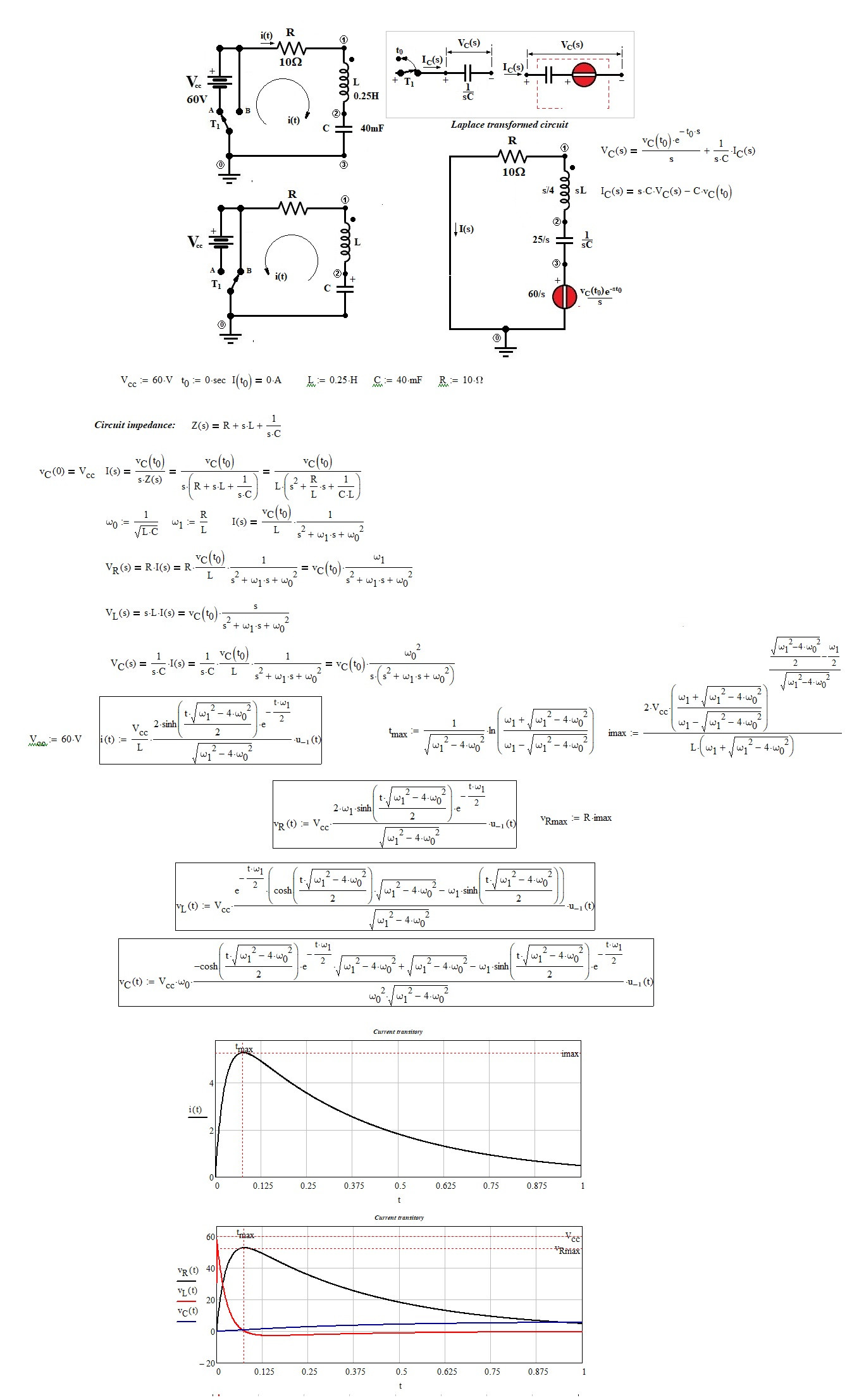
Study of the transient in the series RLC circuit considering zero initial current and charged capacitor:

enter image description here

\$\endgroup\$

Your Answer

By clicking “Post Your Answer”, you agree to our terms of service and acknowledge you have read our privacy policy.

Not the answer you're looking for? Browse other questions tagged or ask your own question.