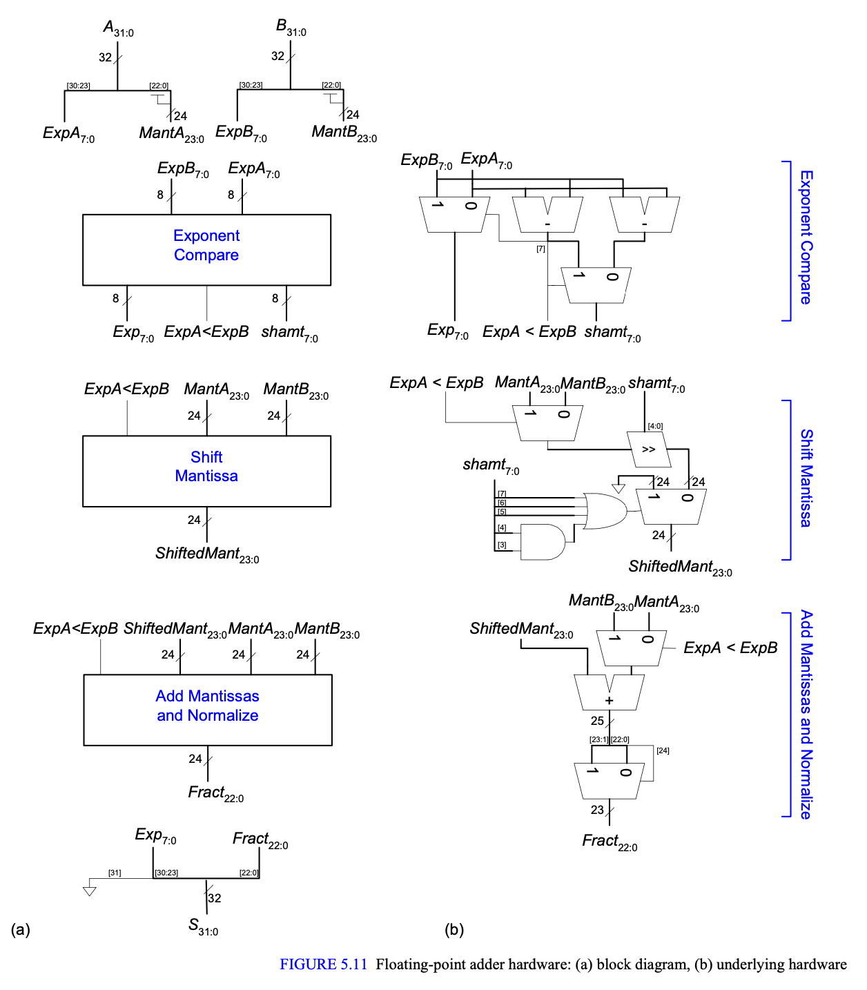
My textbook (Harris and Harris, Digital Design and Computer Architecture) asks us to design a simplified (in that only positive numbers be considered, with NaN and infinities ignored) FP adder block. They provide the following schematic as a solution which I generally follow, except for the Shift Mantissa block:
 It is the final MUX in the Shift Mantissa block (select signal generated by the AND-OR sequence) which I don't understand.
This is certainly not an error as they give the following Verilog for that block:
module shiftmant(input  logic alessb,
                 input  logic [23:0] manta, mantb,
                 input  logic [7:0] shamt,
                 output logic [23:0] shmant);
  logic [23:0] shiftedval;
  assign shiftedval = alessb ?
    (manta >> shamt) : (mantb >> shamt);
  always_comb
    if (shamt[7] | shamt[6] | shamt[5] |
        (shamt[4] & shamt[3]))
        shmant = 24'b0;
    else
        shmant = shiftedval;
endmodule
What is the purpose of this final always_comb block (which corresponds to that final MUX I mentioned above)? Why doesn't our initial shift take care of everything, why do we need the extra logic? I've gone back over the algorithm for FP addition and don't see what this bit of hardware corresponds to.
