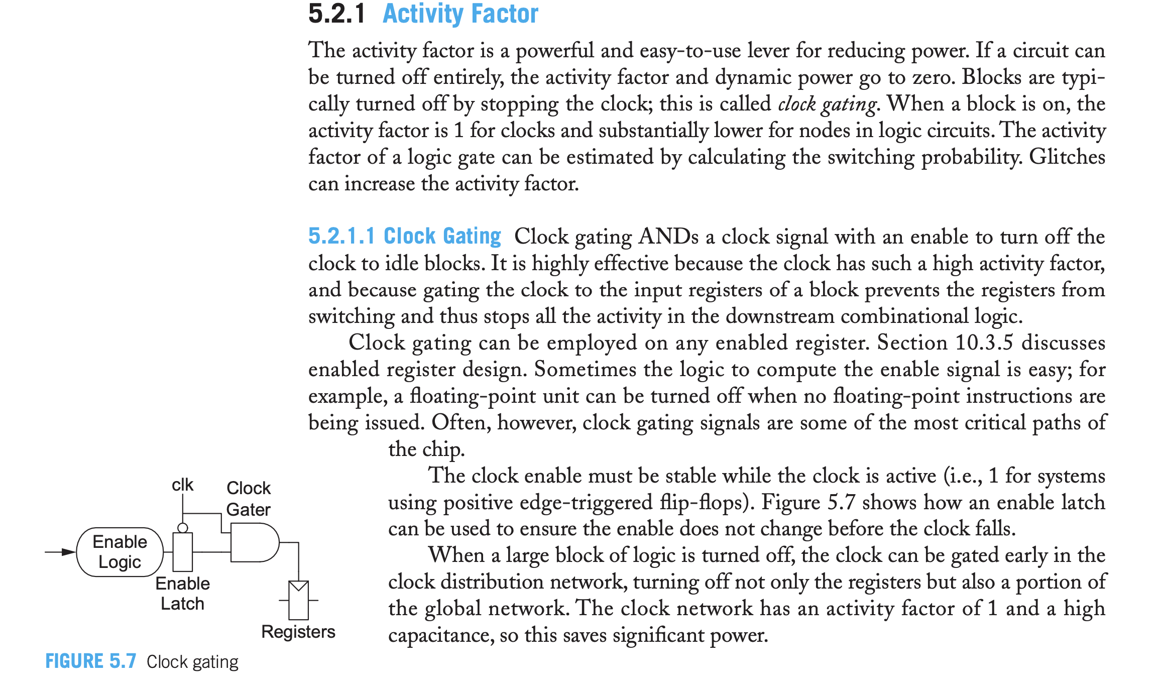
My textbook (CMOS VLSI Design: A Circuits and Systems Perspective, 4th edition, by Weste and Harris) gives the following discussion of a particular method of clock gating into some digital block.
I am trying to understand Figure 5.7 in particular. The somewhat parsimonious explanation given for the method is, again, below:
The clock enable must be stable while the clock is active (i.e., 1 for systems using positive edge-triggered flip-flops). Figure 5.7 shows how an enable latch can be used to ensure the enable does not change before the clock falls.
Why does this "work how we want it to"? The clk signal is doing its usual 50% duty cycle square wave action, and the active-low Enable Latch therefore maintains the output of the Enable Logic block while clk is high. But what would be the problem without the Enable Latch? Is the idea that if the Enable Logic went back high and we didn't have Enable Latch, then we might get violations on the registers (I guess these wouldn't be called hold or setup time violations since the Clock Gater output is not a data input, but a clock input to the registers) around the positive edge of the clock? How does the Enable Latch preclude this? Is this the issue being solved by it?


