1
\$\begingroup\$

schematic

simulate this circuit – Schematic created using CircuitLab

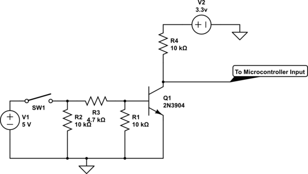
I want to interface a 5v logic signal to an input of a microcontroller (STM32G030) that operates at 3.3V. I made the attached circuit to detect the rising edge of the input 5v signal. However, whenever a nearby AC mains socket switch is flipped, I get an interrupt (I configured the input pin of the microcontroller to generate an interrupt on detection of a falling edge). Can anyone help me improve this circuit and avoid getting such false interrupt detections due to the voltage spikes?

\$\endgroup\$
8
  • 1
    \$\begingroup\$ Why are you not using just resistor divider (5 to 3v3) with some filtering capacitor? Seems transistor is no needed. \$\endgroup\$ Commented Sep 29 at 14:40
  • 1
    \$\begingroup\$ Do you use that 5V logic signal only as an occasional event, something to indicate a change from time to time, or is it going to be a data signal running into hundreds or thousands of pulses per second? \$\endgroup\$ Commented Sep 29 at 14:45
  • \$\begingroup\$ @EdinFifić, the 5v logic signal is to be used occasionally (as an indicator of a shortcircuit event). \$\endgroup\$ Commented Sep 29 at 14:55
  • \$\begingroup\$ @AmritPalSingh What I am trying to understand is if the event will last longer than a milli-second, why not make your MCU detect a LEVEL instead of an edge? That way you can use a capacitor to smooth out a nearby spike and prevent false triggering. \$\endgroup\$ Commented Sep 29 at 15:04
  • \$\begingroup\$ @EdinFifić, Thanks for your valuable feedback! I will certainly try this out. \$\endgroup\$ Commented Sep 29 at 15:18

1 Answer 1

0
\$\begingroup\$

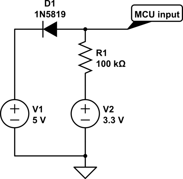
The simplest circuit to get the falling edge for your circuit is the one below:

schematic

simulate this circuit – Schematic created using CircuitLab

It can be used to either detect a relatively slow-falling edge, or a low level input when the 5V supply is off.
The only drawback is a small current flowing from 3.3V to the 5V rail, but in most cases it should not affect anything.
R1 value of 100k should be good enough for almost anything, but you can experiment with resistor values from 10k to 1M, keep that line very short to reduce the effect from nearby voltage/current spikes.
I don't know how much is your +5V rail loaded, you can experiment and see how much voltage will there be when you disconnect the 5V supply line.

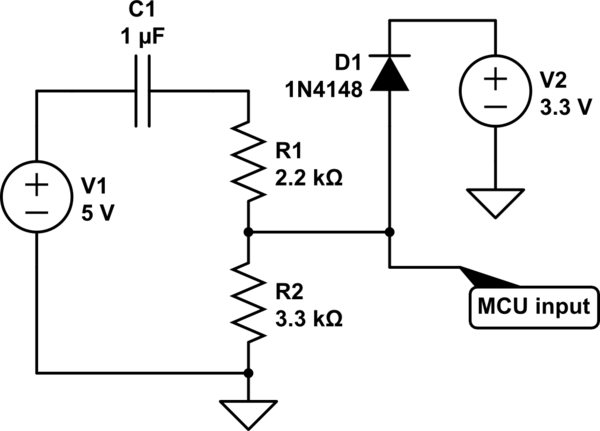
P.S.: I have re-read your question and realized you want a falling edge when the 5V comes UP.
Here is a schematic for that:

schematic

simulate this circuit

C1 can be decreased to 100nF if it will be sufficient for detection by the MCU, or it can be increased if insufficient for detection.

\$\endgroup\$

Your Answer

By clicking “Post Your Answer”, you agree to our terms of service and acknowledge you have read our privacy policy.

Not the answer you're looking for? Browse other questions tagged or ask your own question.