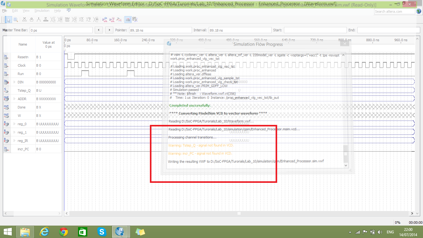
I am trying to simulate a FSM using vector simulator... the state machine variable is called "Tstep_Q", I added it to waveform editor... however, when I start the functional simulation all signals are displayed and change over time except the Tstep_Q signal!! It stays Undefined. While I was trying to resolve this issue I noticed that the simulator is throwing a warning says: "Warning: Tstep_Q - signal not found in VCD." I managed to solve another signal had the same problem "incr_PC" by using the directive /* synthesis keep */, but that was just a regular signal, not a FSM.

module proc_enhanced (Clock, DIN, Resetn, Run, Done, ADDR, DOUT, W);
    input [8:0] DIN;
    input Resetn, Clock, Run;
    output reg Done;
    output [8:0] ADDR;
    output [8:0] DOUT;
    output W;


    // FSM variables
    parameter T0 = 3'b000, T1 = 3'b001, T2 = 3'b010, T3 = 3'b011, T4 = 3'b100;
    reg [2:0] Tstep_Q, Tstep_D;

    // Instructions
    parameter mv = 3'b000, mvi = 3'b001, add = 3'b010, sub = 3'b011,
    ld = 3'b100, st = 3'b101, mvnz = 3'b110;

    // Registers and Wires
    wire [8:0] BusWires;
    wire [2:0] I;
    wire [8:0] IR;
    wire [8:0] R0, R1, R2, R3, R4, R5, R6, R7;
    wire [8:0] A, G;
    reg IRin;
    reg [7:0] Rin;
    reg [7:0] Rout;
    reg Ain;
    reg Gin;
    reg Gout;
    reg DINout;
    reg AddSub;
    wire [7:0] Xreg, Yreg;
    wire [8:0] adr_subr_out;
    reg incr_PC /* synthesis keep */;
    reg ADDRin;
    reg DOUTin;
    reg W_D;

    // Registers
    regn reg_IR (DIN, IRin, Clock, IR);
    regn reg_0  (BusWires, Rin[0], Clock, R0);
    regn reg_1  (BusWires, Rin[1], Clock, R1);
    regn reg_2  (BusWires, Rin[2], Clock, R2);
    regn reg_3  (BusWires, Rin[3], Clock, R3);
    regn reg_4  (BusWires, Rin[4], Clock, R4);
    regn reg_5  (BusWires, Rin[5], Clock, R5);
    regn reg_6  (BusWires, Rin[6], Clock, R6);
    // regn reg_7   (BusWires, Rin[7], Clock, R7); This is replaced with the Program Counter (PC).
    regn reg_A  (BusWires, Ain, Clock, A);
    regn reg_G  (adr_subr_out, Gin, Clock, G);
    regn reg_ADDR (BusWires, ADDRin, Clock, ADDR);
    regn reg_DOUT (BusWires, DOUTin, Clock, DOUT);
    regn reg_W (W_D, 1'b1, Clock, W);
    defparam reg_W.n = 1;

    // Program Counter
    counter PC (Clock, Resetn, Rin[7], incr_PC, BusWires, R7);

    assign I = IR[8:6];
    dec3to8 decX (IR[5:3], 1'b1, Xreg);
    dec3to8 decY (IR[2:0], 1'b1, Yreg);

    // FSM State Table
    always @ (Tstep_Q, Run, Done) begin
        case (Tstep_Q)
            T0:
                if(!Run) Tstep_D = T0;
                else Tstep_D = T1;
            T1:
                Tstep_D = T2;
            T2:
                if(Done) Tstep_D = T0;
                else Tstep_D = T3;
            T3:
                Tstep_D = T4;
            T4:
                Tstep_D = T0;
            default: Tstep_D = 3'bxxx;
        endcase
    end

    // FSM Flip-Flops
    always @ (posedge Clock, negedge Resetn)
    begin
        if (~Resetn)
            Tstep_Q = T0;
        else
            Tstep_Q = Tstep_D;
    end

    // FSM outputs
    always @(Tstep_Q or I or Xreg or Yreg)
    begin
        // initial values
        IRin = 1'b0;
        Rin = 8'b0;
        Rout = 8'b0;
        Gin = 1'b0;
        Gout = 1'b0;
        Ain = 1'b0;
        DINout = 1'b0;
        AddSub = 1'b0;
        Done = 1'b0;
        incr_PC = 1'b0;
        ADDRin = 1'b0;
        DOUTin = 1'b0;
        W_D = 1'b0;

        case(Tstep_Q)
            T0:
            begin
                Rout[7] = 1'b1; // Program Counter
                ADDRin = 1'b1;
            end
            T1:
            begin
                IRin = 1'b1;
                incr_PC = 1'b1;
            end
            T2:
                case(I)
                    mv:
                    begin
                        Rin = Xreg;
                        Rout = Yreg;
                        Done = 1'b1;
                    end
                    mvi:
                    begin
                        DINout = 1'b1;
                        Rin = Xreg;
                        Done = 1'b1;
                    end
                    add, sub:
                    begin
                        Rout = Xreg;
                        Ain = 1'b1;
                    end
                    ld:
                    begin
                        Rout = Yreg;
                        ADDRin = 1'b1;
                    end
                    st:
                    begin
                        Rout = Xreg;
                        DOUTin = 1'b1;
                    end
                    mvnz:
                    begin
                        if (&G != 1'b0) begin
                            Rout = Yreg;
                            Rin = Xreg;
                            Done = 1'b1;
                        end
                    end
                endcase
            T3:
                case(I)
                    add:
                    begin
                        Rout = Yreg;
                        Gin = 1'b1;
                    end
                    sub:
                    begin
                        Rout = Yreg;
                        Gin = 1'b1;
                        AddSub = 1'b1;
                    end
                    ld:
                    begin
                        DINout = 1'b1;
                        Rin = Xreg;
                        Done = 1'b1;
                    end
                    st:
                    begin
                        Rout = Yreg;
                        ADDRin = 1'b1;
                        W_D = 1'b1;
                        Done = 1'b1;
                    end
                endcase
            T4:
                case(I)
                    add, sub:
                    begin
                        Gout = 1'b1;
                        Rin = Xreg;
                        Done = 1'b1;
                    end
                endcase
        endcase
    end

    // Adder/Substractor
    assign adr_subr_out = (AddSub == 0) ? (A + BusWires) : (A - BusWires);

    // Multiplexer
    wire [9:0] MUXsel;
    assign MUXsel[9:2] = Rout;
    assign MUXsel[1] = Gout;
    assign MUXsel[0] = DINout;
    mulpxr bus_multiplexer (MUXsel, DIN, G, R0, R1, R2, R3, R4, R5, R6, R7, BusWires);

endmodule

module mulpxr (sel, DIN, G, R0, R1, R2, R3, R4, R5, R6, R7, BusWires);
    input [9:0] sel;
    input [8:0] DIN, G, R0, R1, R2, R3, R4, R5, R6, R7;
    output reg [8:0] BusWires;

    always @ (*)
    begin
        case (sel)
            10'b0000000001: BusWires = DIN;
            10'b0000000010: BusWires = G;
            10'b0000000100: BusWires = R0;
            10'b0000001000: BusWires = R1;
            10'b0000010000: BusWires = R2;
            10'b0000100000: BusWires = R3;
            10'b0001000000: BusWires = R4;
            10'b0010000000: BusWires = R5;
            10'b0100000000: BusWires = R6;
            10'b1000000000: BusWires = R7;
            default: BusWires = 9'bxxxxxxxxx;
        endcase
    end
endmodule

module regn (R, Rin, clock, Q);
    parameter n = 9;
    input [n-1:0] R;
    input Rin, clock;
    output reg [n-1:0] Q;

    always @(posedge clock)
        if (Rin)
            Q <= R;
endmodule

module dec3to8 (W, En, Y);
    input [2:0] W;
    input En;
    output reg [7:0] Y;

    always @(W or En)
    begin
        if (En == 1)
            case (W)
                3'b000: Y = 8'b00000001;
                3'b001: Y = 8'b00000010;
                3'b010: Y = 8'b00000100;
                3'b011: Y = 8'b00001000;
                3'b100: Y = 8'b00010000;
                3'b101: Y = 8'b00100000;
                3'b110: Y = 8'b01000000;
                3'b111: Y = 8'b10000000;
            endcase
        else
            Y = 8'b00000000;
    end
endmodule

module counter (clk, reset, load, en, D, Q);
    input clk, reset, load, en;
    input [8:0] D;
    output reg [8:0] Q;

    always @ (posedge clk)
    begin
        if (~reset) Q = 9'b0;
        if (load) Q = D;
        if (en) Q = Q + 9'b1;
    end
endmodule
Any clue would be appreciated... I have been trying to figure it out tow days ago!!
