0
\$\begingroup\$

I am working on a project with my MBED microcontroller and I'm running into some snags, because I'm new to it and getting myself confused with how exactly everything works.

I have my MBED hooked up to a 74HC595, which in turn is hooked up to a 7-segment display. I am currently just trying to test the seven segment by creating some sort of counter that goes from 0-9. However, I'm not sure how to do this. Below is my code and how I have it hooked up, I have a few extra declarations in place for the final project, so please just ignore them:
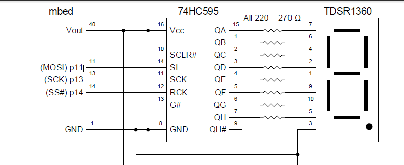
enter image description here

#include "mbed.h"

SPI spi(p11,p12, p13);
DigitalOut red(p25);
DigitalOut green(p26);
DigitalOut cs(p14);
DigitalIn button(p27); //enter
DigitalIn button2(p28); //down
DigitalIn button3(p29); //up

char switchWord;
char record;
int i;

int main() {
  spi.format(8,0);
  while(1) {
    switchWord=0x3F;
    if(button==1)
      switchWord=switchWord^0x06;
    if(button2==1)
      switchWord=switchWord^0x5B;

    cs=0;
    record=spi.write(switchWord);
    cs=1;
    wait(0.01);

    red=0;
    green=0;
    record=record&0x03;

    if(record==1)
      red=1;
    if(record==2)
      green=1;
    if(record==3){
      red=1;
      green=1;
    }
  }
}

Obviously this isn't working how I want it to, I have tried several different ways to get it to count up, and I have been playing with 2's compliment but it's been awhile since I learned about that so I am really fuzzy on it and I couldn't get it to work. Obviously counting up in this set of binary will be different since the 7-segment displays zero when 6/7 LEDs are set to 1, instead of all zeros, so I can't just add the next number or I get a nonsense display. I eventually want to be able to count from 0-9 by hitting the first button, and count down with the second button, but I can't even figure out how to get it to go from 0-1 so if I can get that I think I can get the ball rolling.

I hope this is all clear and I appreciate any help I can get! Thanks!

Alli

\$\endgroup\$
5
  • \$\begingroup\$ Post your full source code and a schematic, how you hooked your uC to the shift register. \$\endgroup\$
    – Golaž
    Nov 4, 2014 at 17:20
  • \$\begingroup\$ You need a mapping table (LUT) that maps digits 0-9 into binary representations. You then shift out those binary values instead of the digits, but increment / decrement the digits (if that makes sense). \$\endgroup\$
    – Majenko
    Nov 4, 2014 at 17:30
  • \$\begingroup\$ Information updated! \$\endgroup\$
    – Alli Reed
    Nov 4, 2014 at 17:30
  • \$\begingroup\$ Majenko, I am kind of understanding what you are saying, I did something similar to that for another project, however, I guess I am still having problems with how exactly the coding for the shift in and out works. \$\endgroup\$
    – Alli Reed
    Nov 4, 2014 at 20:20
  • \$\begingroup\$ I think you're looking for something like this. sweeting.org/mark/blog/2011/11/27/… \$\endgroup\$
    – user57598
    Nov 5, 2014 at 0:49

4 Answers 4

2
\$\begingroup\$

Unless I am missing some important information here regarding what you are trying to do, in order to get the 7-seg to "count" you are going to need to shift into the register the equivalents of each number you want to display in your sequence (0, 1, 2 ... )

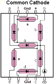
Consider this schematic of a segment display. Although this is likely not exactly how yours is laid out, it will suffice for an explanation.

enter image description here

Doing of few experiments we find that if we connect the register to the display as follows (starting with the registers LSb):

  • 1 -> a
  • 2 -> b
  • 3 -> c
  • 4 -> d
  • 5 -> e
  • 6 -> f
  • 7 -> g

Consider the event in which we shift out a character 5 (00110101), for example. The correct pattern on the display to create the symbol 5 would be:

  • 1 -> a
  • 0 -> b
  • 1 -> c
  • 1 -> d
  • 0 -> e
  • 1 -> f
  • 1 -> g

As you can see, 00110101 -> 1101101 which could be called data conditioning, if you will.

The point of what I am trying to get at here is that you cannot shift out a number or a character, you must in fact manipulate the word based on what data you are trying to display; such work is most simply done with a look-up-table(LUT), as suggested earlier.

For reference, see: The ASCII Table

\$\endgroup\$
1
\$\begingroup\$

Are you expecting your 7-seg display to understand ASCII or to be able to interpret binary numbers into a symbol to display? That's not how 7-seg displays work.

You're driving each individual segment of the display, so you decide on what pattern of segments to light up. You choose a pattern for each digit you want to display.

When you say that it displays a zero when 6/7 LEDs are set to 1, this is perfectly normal & expected behavior. Count the number of segments which are lit up. - '1' requires 2 segments - '2' requires 5 segments - '3' also requires 5 segments, but not the same set as a '2' - etc ...

You could also add on a decoder IC - something like a 74HC4511 would work - to do that job for you. It takes a 4-bit BCD input and produces the correct combination of outputs to drive all of the segments and display recognisable digits.

\$\endgroup\$
1
  • \$\begingroup\$ Me figuring this out leads into a project I am doing for a class so I have to use the components given, I have it hooked up to a shift register and it does read the hexadecimal inputs that I am giving it, and I understand how the LEDs are lighting up. What I am trying to figure out is how to make the LED count up. \$\endgroup\$
    – Alli Reed
    Nov 4, 2014 at 20:17
1
\$\begingroup\$

the TDSR1360 is a common-anode display, so to make the segments light up they must be grounded through individual resistors while the display's anodes are connected to Vcc.

In order to do that, each segment must be connected to a 595 output, through a resistor, and will only light when that 595 output goes low.

One way to map the segments for the digits "0" through "9" to the 595's outputs is like you've shown, but with the display's anodes (pins 3 and 8) connected to Vcc instead of to ground.

Then, in order to make the display count up, what you must do is serially shift a byte which corresponds to, say, "0" into the 595, and then assert RCK. That'll broadside load the byte into the 595's parallel outputs and light up the segments which correspond to "0".

Next, you'll shift in a byte which corresponds to "1", assert and deassert RCK, and the display will now read "1".

Next, you'll shift in the byte which corresponds to "2", assert and deassert RCK, and the display will now read "2".

Continuing on with the bytes corresponding to 3 through 9 will make it seem like the 595 is counting up, when all it's really doing is sequentially displaying canned bit sequences arranged to display digits.

\$\endgroup\$
1
\$\begingroup\$

Perhaps I'm blind, but I don't see the translation table in your code that translates between the integer holding your counter and the pixel-pattern of the glyph that represents that digit.

// ...
int counter=0;
char translation_table[] = {
    0b11110111; // 0
    0b00001100; // 1
    // ... fill in details here ...
};
while(1) {
    counter=counter+1;
    // FIXME: do something about overflow
    char LED_pattern = translation_table[counter];
    cs=0;
    record=spi.write( LED_pattern );
    cs=1;
    wait(0.5);
    // ...
}

The "translation_table" mentioned in the above code is also called the

\$\endgroup\$

Your Answer

By clicking “Post Your Answer”, you agree to our terms of service and acknowledge you have read our privacy policy.

Not the answer you're looking for? Browse other questions tagged or ask your own question.