It kinda looks like schmitt trigger but i couldn't understand the parallel diode resistor part. Is it possible to analyse this circuit with node-voltage method?

It kinda looks like schmitt trigger but i couldn't understand the parallel diode resistor part. Is it possible to analyse this circuit with node-voltage method?
Rather it resembles a bilateral diode limiter... but in no case it is a Schmitt trigger because there is no positive feedback... there is only a negative feedback in an inverting configuration.
Well, let's try to see what the basic idea is behind it, and to analyze its operation (please, participate in this explanation).
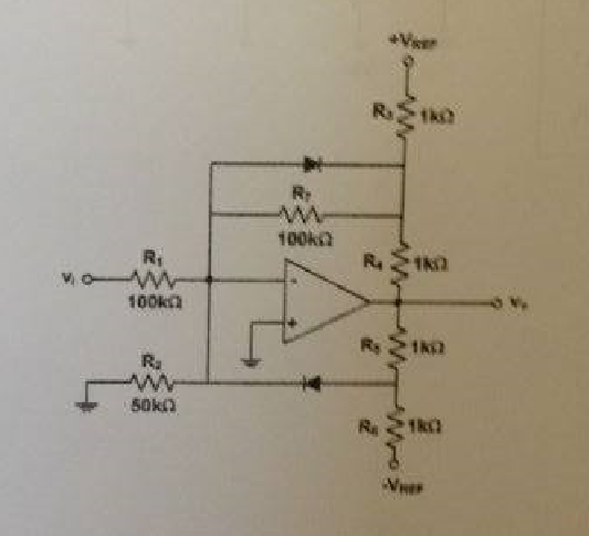
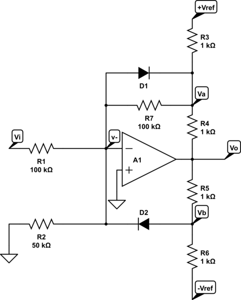
First we see an inverting amplifier (R1 = R7 = 100 k and the op-amp) with a gain of -1. For now we do not understand why R3 is connected not just in the output of op-amp... but maybe later we will understand. Also, for now, we do not understand what is the role of the resistor R2 = 50 k... but maybe we will understand this later ... just we should not be discouraged:)
Then we see two voltage dividers: R3,R4 - connected between the op-amp output and the positive rail; R5,R6 - between the op-amp output and the negative rail. It seems their outputs produces reference voltages (thresholds) for the series diode limiters.
The diodes are virtually grounded. So, when the input voltage is between the two thresholds they are off... there is a virtual ground... and the circuit is an inverter (Vout = -Vin).
Now imagine the input voltage increases enough so the output voltage of the upper voltage divider R3,R4 goes down below the zero. The upper diode turns on and diverts the input current directly into the op-amp output... so the output voltage stops changing... and this is the high threshold.
Similarly, if the input voltage decreases enough so the output voltage of the lower voltage divider R5,R6 goes up above the zero, the lower diode turns on and diverts the input current directly from the op-amp output... so the output voltage stops changing... and this is the low threshold.
Note that always there is a negative feedback (either through R7 or the upper or lower diode)... and the op-amp never saturates.
But I still can't understand what is the role of the resistor R2 (50k). One explanation can be that it "helps" the input source passing an additional current from/to the ground...

simulate this circuit – Schematic created using CircuitLab
Hello,
I found this circuit a pretty challenging exercise for my students. I also noticed that the accepted answer may have been a bit incomplete, so I thought I'd add my two cents here.
First, we can determine that this circuit does indeed have negative feedback. The output is connected through R4 and R7, R4 and D1 or R5 and D2 to the negative input. Current can flow both ways, so there is always a path to enable negative feedback. If we can combine this with the incredibly high gain from op amp A1, we can state that v- = 0V due to the virtual short circuit between the inputs of the op amp.
This also explains that R2 is actually not needed for the operation of this circuit, as the voltage across R2 always remains 0V.
Finding the easy point
When the input Vi=0V, no current flows through R1 (v-=0V too). This also means there is no current through R7 either, and the voltage at Va needs to be kept at 0V by the output in order to make this all work. The current through R4 is then equal to the current through R3, so the voltage at the output is then
\$i_{R3}=\frac{Vref-Va}{R3}=\frac{Vref}{R3}\$
\$Vo=0V-R4\cdot i_{R3}=-\frac{R4}{R3}Vref\$
Note that Vb is at a negative voltage, and so cannot influence v- in any way. That's why it also doesn't affect the output of the op amp! We can still calculate Vb though to be:
\$Vb=\frac{Vo\cdot R6 - Vref\cdot R5}{R5 + R6}<0\$
Increasing Vi
When we increase Vi, a current starts to flow through R1 towards v- which is kept at 0V by the negative feedback. This current will go through R7 and D1, and decreases the voltage at Va. If we assume D1 to be ideal, then most current will flow through D1 and keep Va at 0V (in practice around -0.6V~-0.7V but we'll take 0V to make it easier). The current through R4 is then the sum of the currents through D1, (R7 but this is pretty much shorted by D1) and R3. We can then calculate the output using just this information:
\$i_{R1}=i_{D1}=\frac{Vi-v_{-}}{R1}=\frac{Vi}{R1}\$
\$i_{R3}=\frac{Vref-Va}{R3}=\frac{Vref}{R3}\$
\$Vo=0V-R4\cdot i_{R4}=-R4\cdot (i_{D1}+i_{R3})=-R4\cdot(\frac{Vi}{R1}+\frac{Vref}{R3})\$
Decreasing Vi
When we decrease Vi, the situation becomes a bit more complex. Current will now flow from v- to Vi. Both diodes will now become reversely biased, so all that current from R1 will flow through R7. The voltage Va can then easily be determined (remember that \$Vi < 0\$):
\$Va=R7\cdot i_{R7}=R7\cdot i_{R1}=-Vi\frac{R7}{R1}\$
The output is a little bit more annoying, as it depends on the current through R4, which is now \$i_{R3}-i_{R7}\$. I did it with the help of a computer, I hope it's correct:
\$Vo=-\frac{R4}{R3}Vref-\frac{Vi}{R1}\left(R7\frac{R4}{R3}+R7+R4\right)\$
At the same time, the voltage at Vb will rise as well, and can still be calculated with the same equation as before.
Decreasing Vi more
Decreasing Vi will increase Va, Vo and Vb. As Vb increases, it will reach a point where D2 becomes forwardly biased. At that point, Vb cannot go higher than 0V, as it would pull v- along which would violate our virtual short-circuit between the inputs of the op amp.
Unfortunately, the situation becomes very complex now. The current will still go through R1 from v- to Vi, but it will come from both R7 and D2, leading to some very long equations. One can reason though that because R7 is very big, that the current through R7 is most likely insignificant compared to that of D2. In this case, one can write:
\$\frac{Vo}{R5}=-\frac{Vi}{R1}+\frac{Vref}{R6}=>Vo=-\frac{R5}{R1}Vi+\frac{R5}{R6}Vref\$
I hope I didn't make a mistake in my formula's. I just noticed that everyone kept saying the output stops changing, but this is actually not the case... In the following image you can also see the simulation result that demonstrates these three zones: - On the right we have D1 working, Va is kept at 0V - In the middle, we have neither D1 or D2 conducting, so we have a big gain due to R7 being used - On the left we have D2 starting to work causing Vb to be kept at 0V.