1
\$\begingroup\$

I have a microcontroller outputting a ramp signal on an I/O pin in PWM form. i.e. the duty cycle steadily increases from 0% to 100%, then drops to zero and repeats. After smoothing I end up with a sawtooth-like wave (except of course the sudden drop to zero takes a bit of time due to the filter).

My microcontroller code uses a 1kHz interrupt and upon every interrupt decides whether the output should be high or low based on a) the current progress through the ramp, and b) for how many interrupt cycles the output pin has already been high or low.

This is all fine and dandy, and it works well for my application, but I need a faster solution.

Something tells me this should be realizable with a pure logic circuit rather than with firmware code. After all, we have a steady clock pulse and a steady increase from 0% duty to 100% duty. But I'm struggling with the implementation concept.

Can anyone think of a way to do this with logic gates, so that I can write this onto an FPGA/PLD and have many (much faster) waves being generated?

--

NB: To complicate matters, frequency must be adjustable. In my MCU code this is as simple as having a variable representing how many samples the ramp should last for.

\$\endgroup\$
3
  • \$\begingroup\$ Do you really need the pwm or is a frequency adjustable sawtooth generator what you are looking for? \$\endgroup\$
    – PlasmaHH
    Commented Mar 26, 2015 at 12:13
  • \$\begingroup\$ Well yes, a different solution for producing many frequency and amplitude selectable sawtooths at a few hundred Hz and at minimal cost and PCB footprint would be welcomed! \$\endgroup\$
    – PanicBear
    Commented Mar 26, 2015 at 12:22
  • \$\begingroup\$ which uC are u using? \$\endgroup\$ Commented Mar 26, 2015 at 12:23

5 Answers 5

3
\$\begingroup\$

Low pass filtered PWM can do what you want, but you need the PWM frequency to be much higher than 500 Hz.

Yes, you can get hard-wired logic to do some of this task. Use the PWM hardware built into most microcontrollers. If yours doesn't have any PWM outputs, go use one of the many many micros that do.

PWM hardware in the micro will take care of producing the individual pulses for you. All you have to do is set the duty cycle, and the hardware takes it from there. Let's say the micro can clock the PWM hardware at 10 MHz (very easy to get), and that you want 8 bit resolution. That means each PWM pulse will take 255 clock cycles, which is 25.5 µs, which comes out to a frequency of 39 kHz. That is much easier to low pass filter to remove the 39 kHz pulse frequency but still leave a reasonable number of harmonics of the signal you want.

You can now update the duty cycle in the hardware register independently of the individual PWM pulses. With the right kind of PWM hardware, a new duty cycle will take effect at the start of the next period. However, if your periods are 255 instruction cycles long, then you can easily interrupt once for each one, adjusting the duty cycle each pulse.

To compute the desired duty cycle, use a byte or two or three of fraction bits below the integer duty cycle byte. For example, you can use a 32 bit counter which you think of as the high byte of the actual duty cycle you write to the hardware, and the low 24 bits as the fractional part for intermediate calculations. For whatever ramp speed you want, calculate the amount to add to this 32 bit value up front. Higher increment values will result in faster ramps. Each interrupt, add the increment into the 32 bit counter, then take its high byte and write it to the hardware PWM duty cycle register. Even a 8 bit micro can easily accomplish this in well under 255 instruction cycles.

\$\endgroup\$
1
\$\begingroup\$

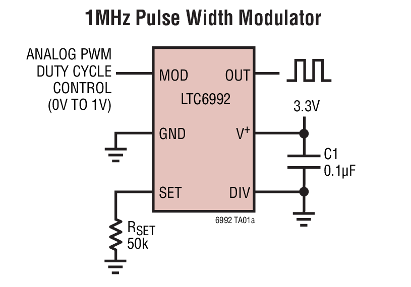
Maybe consider using this very simple chip: -

enter image description here

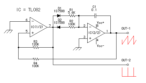
All you need to feed into it is a sawtooth signal generated by a couple of op-amps: -

enter image description here

Take the output from the op-amp and reduce it via a potential divider to give 0 to 1V output suitable for inputting to the LT6992's analog PWM duty cycle control input. The LT6992 can produce a PWM waveform from low Hz to 1MHz.

\$\endgroup\$
1
\$\begingroup\$

You will need a counter and a (digital) comparator for this. Just count upwards (let the counter roll back over to 0) and compare the output of the counter to your input value. You may need to adjust the clock frequency of your counter to get an appropriate PWM frequency.

rough schematic

\$\endgroup\$
0
\$\begingroup\$

Logic circuits won't (really) work here as it is not a digital circuit but an analog one.

\$\endgroup\$
0
\$\begingroup\$

A simple way to generate a PWM ramp wave digitally is to have two divide-by-N circuits with slightly-different periods (they could be reloadable counters, counters with a terminal-count compare circuit, feedback shift registers which reset when a particular value is reached, or any of a number of other things), along with a circuit which sets an output high when it receives a pulse from the first circuit and low when it receives a pulse from the second. The "PWM rate" will be roughly the average period of the two counters, and the sawtooth output period will be the product of the two periods divided by the difference (e.g. counters which count 997 and 1004 pulses at 1MHz will have a PWM period of about 1000.5us, and generate a sawtooth wave with a period of about 142998Hz (about 7Hz).

\$\endgroup\$

Your Answer

By clicking “Post Your Answer”, you agree to our terms of service and acknowledge you have read our privacy policy.

Not the answer you're looking for? Browse other questions tagged or ask your own question.