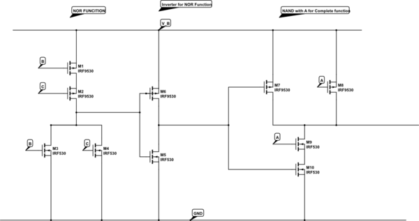
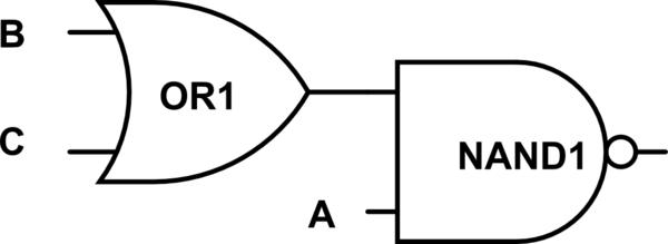
I wanted to implement the function:
$$Y = \neg (A \land (B \lor C))$$
This is what I came up with, it looks correct to me but I would like a second opinion on that.

simulate this circuit – Schematic created using CircuitLab
I wanted to implement the function:
$$Y = \neg (A \land (B \lor C))$$
This is what I came up with, it looks correct to me but I would like a second opinion on that.

simulate this circuit – Schematic created using CircuitLab
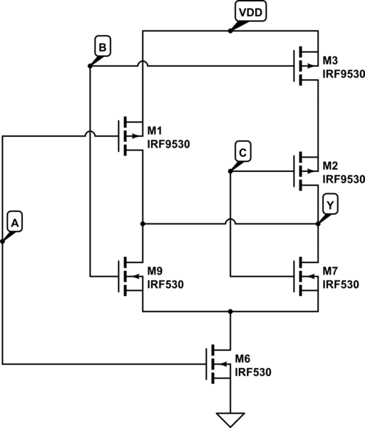
From your drawing, I derive this:

simulate this circuit – Schematic created using CircuitLab
Your 10T implementation is correct.
There are alternative 6T implementations as an OAI complex gate:

The OAI could be as drawn or the nFETs can be rearranged.
(Note that the bulk nodes of the stacked FETs are drawn inappropriately. I didn't intend to imply these are discrete ICs with the source and bulk nodes shorted... this is just what I pulled from the library.)