-1
\$\begingroup\$

I needed to build a delay circuit so I'm following this guide: http://www.learningaboutelectronics.com/Articles/555-timer-delay-before-turn-on-circuit.php
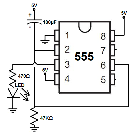
schematic

Using this circuit, I get a delay of about 5 seconds before the LED turns on. The only big difference is the output of the 555 is going into the gate of a IRFZ44N MOSFET as I needed more power.

The MOSFET source is hooked to ground, and the drain is hooked to a 330 Ohm resistor -> LED -> 5V.

However, with 5V input voltage, I can only get 3V across the drain and source. How could I improve this circuit to give me more efficiency, closer to my 5V?

EDIT: I'm following the schematic from the guide. It's exhibiting the same behavior as the guide, so the timing circuit should be correct. The only difference is the MOSFET. I also added a 330 Ohm resistor between the 555 pin 3 output and MOSFET gate and now I'm getting full voltage from drain. Looks like the gate was leeching some voltage.

\$\endgroup\$
6
  • \$\begingroup\$ Here is a comment, replace the word "here" with "you", replace "is" with "should make" and replace "a comment" with "a proper schematic". \$\endgroup\$ Commented Apr 12, 2018 at 3:33
  • 1
    \$\begingroup\$ Well, this is a pretty simple circuit. Most of the schematic is there. In the meanwhile, I think I solved the issue by moving the resistor between the 555 and gate. I'm getting the full 5V. Closing this. \$\endgroup\$
    – DTOAL
    Commented Apr 12, 2018 at 4:04
  • \$\begingroup\$ It would be nice if you add a schematic instead of a snap of the breadboard connection! \$\endgroup\$
    – CNA
    Commented Apr 12, 2018 at 4:05
  • \$\begingroup\$ Yes, the snap was a bad idea. \$\endgroup\$
    – DTOAL
    Commented Apr 12, 2018 at 4:14
  • 1
    \$\begingroup\$ I don't see any MOSFET in that schematic. \$\endgroup\$
    – user39382
    Commented Apr 12, 2018 at 4:24

1 Answer 1

1
\$\begingroup\$

Vgs(th) is when it barely conducts at Vgs=2~4V so you need 2.5x to 4x this value minimum RdsOn for low Vds at high current.

Since Vout is Bipolar it is not rail to rail. So either use a sub-threshold FET or V=+12

\$\endgroup\$

Your Answer

By clicking “Post Your Answer”, you agree to our terms of service and acknowledge you have read our privacy policy.

Not the answer you're looking for? Browse other questions tagged or ask your own question.