1
\$\begingroup\$

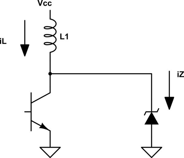
In this circuit there are several things required like the inductor and diode current, and the average power of the inductor, but what does really puzzle me is how can calculate the zener average power?

schematic

simulate this circuit – Schematic created using CircuitLab
I understand that the average power of any inductor is zero, but I don't know for the zener. The inductor current is

$$i_{L}=\frac{1}{L}\int V_{CC}dt$$
and this would be the same current on the zener because when the transistor turns off the diode try to maintain the inductor current and breaks down.

The instantaneous power of the diode is \$I_{z}V_{z}\$ , but which is the average power?

\$\endgroup\$
3
  • 1
    \$\begingroup\$ The symbol you show is for a Schottky diode, not a zener. If the transistor is always switching ON-OFF, the maximum time for both ON and OFF is a 50% duty cycle. \$\endgroup\$
    – user105652
    Commented Dec 24, 2018 at 4:42
  • 1
    \$\begingroup\$ I agree with @spar \$\endgroup\$
    – Zed K.
    Commented Dec 24, 2018 at 5:56
  • 1
    \$\begingroup\$ As you see in my analysis @Sparky256 's answer is true for a 10V Zener. Then the inductor current ramp down time is also triangular thus average Power is ½Vcc*Ip and it being Avalanche or Zener or TVS or MOV is somewhat irrelevant. unless we consider bulk resistance and RdsOn which are assumed low voltage drops. \$\endgroup\$
    – D.A.S.
    Commented Dec 24, 2018 at 19:44

3 Answers 3

3
\$\begingroup\$

I think you have to consider two situations. In discontinuous conduction mode the entire energy in the inductor (ideally) gets dissipated by the zener each off period.

The current in the inductor increases as i(t) = tV/L , so the energy at the end of the charge time \$t_{ON}\$on is

E= \$\frac{t_{ON}V^2}{2L}\$

In continuous conduction mode there is still some current flowing in the inductor at the end of the off period, so the current increases linearly from the initial current and the energy that goes into the zener is proportional to the differences of the squares of the initial and final currents. So in steady state there is some constant amount of energy stored in the inductor at the end of each off time.

\$\endgroup\$
2
\$\begingroup\$

Rev A.

Symbol used is a Schottky Power Diode, which are Avalanche type clamps but like Zeners use the same notation for current, \$i_Z\$

Although the energy stored in current in the Inductor is released into the Zener E= ½ LI² , I(t) is a ramp and not constant.

But what is the Power Dissipation?

Yet we know when the transistor is switched off, Iz=IL and for now, if we let Vce(sat)=0, the voltage across the inductor = 5V , thus the final power input while the ramp reaches a peak current , Ip is P = ½ VIp ( triangle is ½ the area of the VI product square)

The Zener will discharge the current faster but with a fast step voltage and some triangular ramp decay time. {edit} The discharge time depends on the voltage ratio. THe inductor Ramp times will be equal when the voltage across the inductor is equal and opposite polarity or Vz=2Vcc

V=LdI/dt and both L and dI=Ip are constants at time Tu=dt of current ramp up for the ramp-down time, Td.

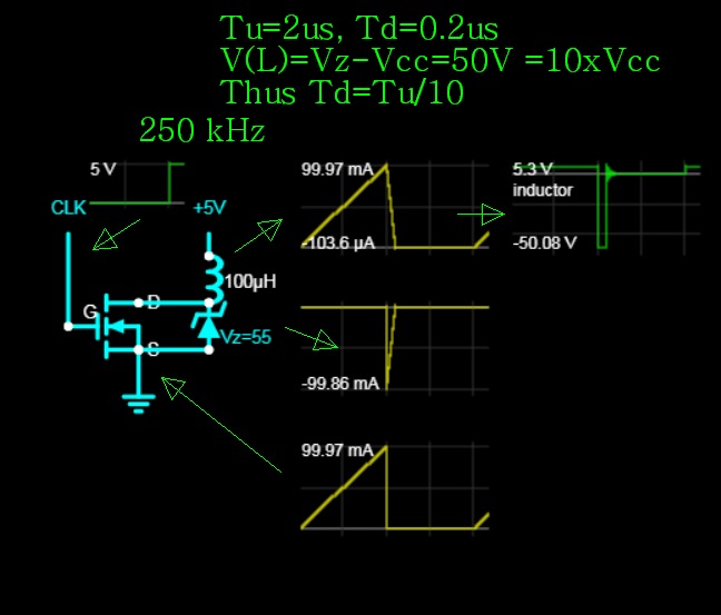
The discharge time duration Td = Vcc/Vz * T \$Td/Tu=\dfrac{Vz-Vcc}{Vcc}\$

We already concluded Vdt = LIp = some fixed value.

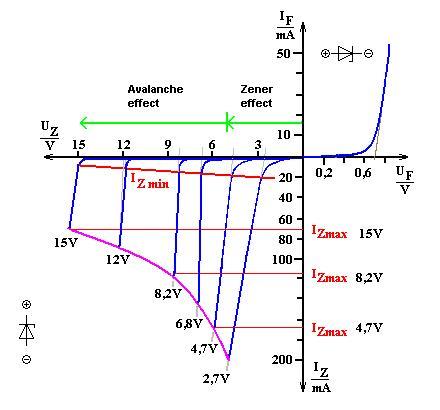
Although the semiconductor doping of Avalanche diodes is lighter, has a higher breakdown voltage, is faster and has a different conduction mechanism, the notation for such diodes often still uses \$i_Z\$.

Simulation proof

enter image description here Other info enter image description here

\$\endgroup\$
8
  • 1
    \$\begingroup\$ I(t) is NOT a ramp during the Zener dissipation (hint: it's not an LR discharge curve). As the field collapses the current is kept almost constant. Avalanche diodes such as Schottky diodes are NOT Zeners, they are avalanche diodes. \$\endgroup\$ Commented Dec 24, 2018 at 17:46
  • 1
    \$\begingroup\$ So you are saying it is an equally square current pulse? Does that mean Td = Vcc/Vz * T is wrong and should be Td = ½ of this \$\endgroup\$
    – D.A.S.
    Commented Dec 24, 2018 at 18:10
  • 1
    \$\begingroup\$ In addition the Zener does not discharge the current quicker. The Zener dissipates the energy stored quicker (VIt). \$\endgroup\$ Commented Dec 24, 2018 at 18:10
  • 1
    \$\begingroup\$ No it's not absolutely square. However consider the difference between a diode where the current is described by LR and a Zener where the current is described by both LR and the dominant VI of the Zener. As the field collapses in the inductor the current tends to remain constant where the Zener is in place. Read the app notes I linked to. \$\endgroup\$ Commented Dec 24, 2018 at 18:15
  • 1
    \$\begingroup\$ is this wrong? Td/Tc=Vcc/Vz for some loosely defined avalanche voltage Vz \$\endgroup\$
    – D.A.S.
    Commented Dec 24, 2018 at 18:17
2
\$\begingroup\$

Set a couple of parameters first:

  1. Vz > VCC
  2. I(L) is steady state current

I(L) = VCC / Inductor_Resistance

The energy stored in the magnetic circuit is:

E(Joules) = 1/2 * L * I^2

This is the total energy dissipated in each on/off transition.

You need values for L, R, VCC, Vz and on/off repetition rate then you can calculate the time taken to discharge the energy stored in the inductor and the power dissipated in the Zener and the series R.

With the Zener you have instantaneous dissipation equal to (Vz - Vcc) * I(L) so the higher the value of Vz the faster you dissipate the energy in the inductor.

A really decent explanation is in this Maxim Appnote and ST Appnote. They describe using a Zener/FET combination, but the formula work for just a Zener too.

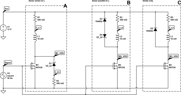
Update: It is interesting to see the impact on the time taken to dissipate the inductor stored energy. Below is the three common configurations:

  1. A diode across the inductor
  2. A zener plus a diode across the inductor (some use a TVS)
  3. A zener in series with the inductor

schematic

simulate this circuit – Schematic created using CircuitLab

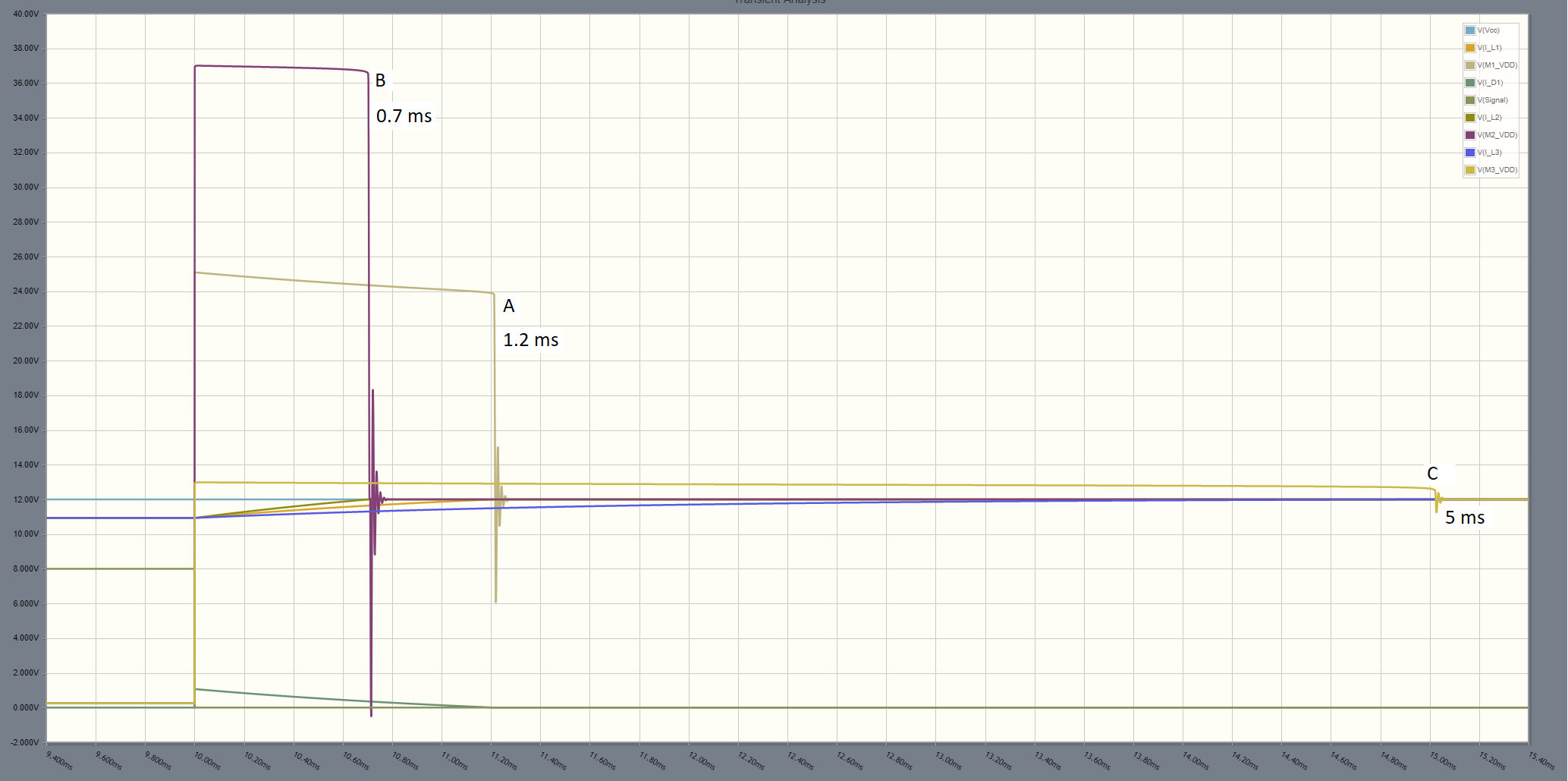
enter image description here

For the component values I used, the waveforms show that configuration B provides the shortest time to dissipate the energy in L, since it is ONLY dissipating the energy in L.

In configuration B the Zener dissipated twice the energy stored in L since it must dissipate an equal amount of energy from the power supply.

In configuration C the energy is mainly dissipated in the resistance associated with L so the time is approximately 5(LR).
\$\endgroup\$

Your Answer

By clicking “Post Your Answer”, you agree to our terms of service and acknowledge you have read our privacy policy.

Not the answer you're looking for? Browse other questions tagged or ask your own question.