13
\$\begingroup\$

I am a bit confused about the physical meaning of negative resistance.

Mathematically, a component which has negative resistance shows a decreasing voltage across its terminal when the current inside it grows, and vice versa. But how is this physically possible?

Somewhere I have read that an example of component with negative resistance is a voltage source. But I do not understand this statement, since a voltage source is a component which at most shows a (positive) internal resistance.

\$\endgroup\$
7
  • 1
    \$\begingroup\$ Maybe if you see a circuit with two resistors in series (voltage divider), having in the middle 2.5V, a component with negative resistance can be said to 'add voltage' instead of removing voltage... but I leave a real answer to the experts here ;-) \$\endgroup\$ Commented Apr 25, 2019 at 16:11
  • 1
    \$\begingroup\$ Minus R will provide power, not dissipate power. \$\endgroup\$ Commented Apr 25, 2019 at 16:41
  • 1
    \$\begingroup\$ There are two types 'S' & 'N'. en.wikibooks.org/wiki/Circuit_Idea/… \$\endgroup\$ Commented Apr 26, 2019 at 3:10
  • 1
    \$\begingroup\$ A voltage source does not have negative resistance, it has ZERO resistance. If you have such a device, take care not to short it out with a zero ohm resistor. I cannot compute the power dissipated in such a circuit. \$\endgroup\$ Commented Apr 26, 2019 at 5:43
  • 1
    \$\begingroup\$ Arc discharge is modelled as a negative resistance. \$\endgroup\$
    – KalleMP
    Commented Apr 26, 2019 at 19:25

12 Answers 12

3
\$\begingroup\$

Although the negative resistance is veiled in mystery, in fact it is a quite simple concept. It can be easily explained by analyzing the voltage drops across resistances.

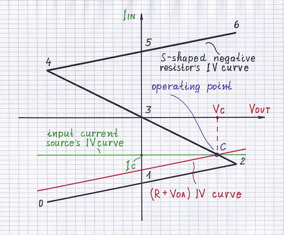
The positive resistor subtracts its voltage drop from the input voltage thus decreasing the current while the (S-shaped) negative resistor adds its voltage drop to the input voltage thus increasing the current. So the positive resistance impedes while the negative resistance helps the current.

The main question is, "How does the negative resistor add its voltage?" There are two techniques to do it leading to the two kinds of negative resistance - differential and absolute.

Negative differential resistor is, in essence, a positive resistor that subtracts its voltage drop V = I.R from the input voltage. But in contrast to the positive resistor that has constant resistance, it is a dynamic resistor that significantly decreases its resistance when the current slightly increases. As a result, instead to increase, the voltage drop (the product of the increasing I and the more vigorously decreasing R) decreases... and this is equivalent to adding voltage. This is the trick - reducing the loss is actually a profit.

S-shaped NDR - operation

See also: Demystifying the Negative Differential Resistance Phenomenon

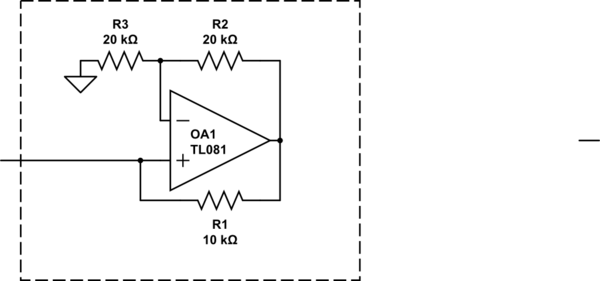
Absolute negative resistance is done in a more natural way - by a dynamic voltage source (electronic circuit). It changes its voltage proportionally to the current (like a positive resistor) but adds it to the input voltage (instead to subtract). For the purpose of addition, this voltage has an opposite polarity; hence the name of this circuit - “voltage inversion negative impedance converter” (VNIC).

enter image description here

See also: Investigating the Linear Mode of Negative Impedance Converters with Voltage Inversion

So, the "physical meaning of negative resistance" is "dynamic resistor" or "dynamic source". But what is the point of all this? What negative resistance can be used for?

Negative resistance can compensate equivalent positive resistance. For example, if we connect an S-shaped negative resistor in series to a positive resistor with the same resistance, the equivalent resistance will be zero. Figuratively speaking, the negative resistance has "destroyed" the positive resistance and the combination of two resistors acts as a piece of wire. Mathematically, it is simply R - R = 0… but we, human beings, need a more "physical" explanation... and there it is:

  • Differential negative resistance. If the input source tries to increase the current, the voltage drop across the positive resistor increases and it should affect the current. But the negative resistor vigorously decreases its resistance to reduce the voltage drop across itself by the same value. The total voltage across the whole network (R and -R in series) does not change; it behaves like a Zener diode with zero differential resistance. So the differential negative resistor compensates the change of the voltage drop across the positive resistor... not the very drop.
  • Absolute negative resistance. It compensates the absolute voltage drop across the positive resistor (not only the change) by inserting the same voltage. For this purpose, it uses an additional voltage source with opposite polarity. The total voltage across the whole network is not only constant but zero. The network really behaves as a "piece of wire" and does not impede the current. Popular examples of this arrangement are the transimpedance amplifier and inverting amplifier in which the op-amp output acts as an absolute negative "resistor". It destroys the feedback resistance by compensating the voltage drop across it with equal voltage.

The ordinary voltage source is not a negative "resistor" since its voltage does not change proportionally to the current... it is not dynamic source... it is a constant voltage source. So, if we connect it in series with a resistor, it will compensate only a part of the voltage drop across the resistor equal to its voltage.

It is likely the related discussion in ResearchGate will be of interest to you:

And why are there two more types of negative resistance?

\$\endgroup\$
22
\$\begingroup\$

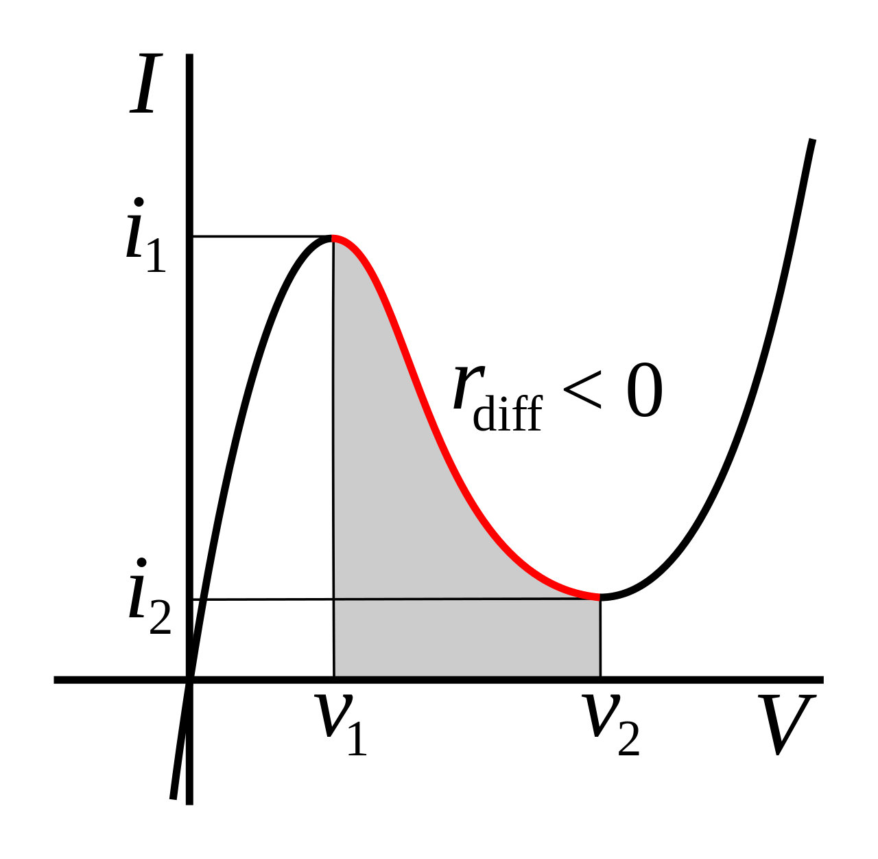
There are a number of mechanisms that result in a region where locally increasing voltage results in locally decreasing current. For example, an Esaki (tunnel) diode.

enter image description here

A common example would be a switching power supply with a steady load. Assuming the efficiency is more-or-less constant, increasing the input voltage results in less current being drawn. It is always consuming energy though.

A stand-alone component that exhibits negative resistance (rather than negative differential resistance) is not possible without some kind of energy source within the component, otherwise it would violate conservation of energy (\$P = E^2/R\$) and negative P would indicate it is acting as a power source.


If you want to play with a negative resistance effect, one way (assuming you don't mind one end being grounded) is to use a negative impedance converter:

schematic

simulate this circuit – Schematic created using CircuitLab

The above circuit acts like a -10K resistor with one end grounded (within its linear range), and works down to about zero volts. Any power it produces comes from the op-amp supplies.

\$\endgroup\$
4
  • 2
    \$\begingroup\$ That is really a fine choice of an example device you picked. \$\endgroup\$
    – The Photon
    Commented Apr 25, 2019 at 16:23
  • \$\begingroup\$ @ThePhoton LOL, great minds and all that. \$\endgroup\$ Commented Apr 25, 2019 at 16:45
  • 2
    \$\begingroup\$ @J... No, it really is negative differential resistance. You put a stiff voltage across it and keep it from oscillating the current will follow that curve. See, for example, DC Characterization of Tunnel Diodes Under Stable Non-Oscillatory Circuit Conditions by Wang et al. \$\endgroup\$ Commented Apr 25, 2019 at 18:31
  • 1
    \$\begingroup\$ This is an example of a "type N" device. There are also "type S" devices. \$\endgroup\$ Commented Apr 26, 2019 at 5:46
5
\$\begingroup\$

In this context, we have to discriminate between (1) pure differential (dynamic) neg. resistances (as shown in the examples of the other answers) and (b) a static negative resistance.

For a differential neg. resistance (rdiff) the current CHANGES are negativ, for a static neg. resistance the CURRENT itself has a negative sign.

My following answer concerns only the static negative resistor:

Such an element does not "consume" a current - driven by a voltage source, but - the other way round - it drives a current (prop. to the voltage) in an opposite direction into the voltage source.

Hence. it is a voltage-controlled current source. For such circuits only active realisations are possible (using transistors or - in most cases - opamps). The most popular circuit is the NIC (Negative-Impedance Converter).

\$\endgroup\$
4
\$\begingroup\$

But how is this physically possible?

Some components, like Esaki diodes and glow tubes, have an I-V curve that is entirely in the I and III quadrants, but has a negative slope region over a limited range. In this region, a small-signal model of the device will have negative resistance.

enter image description here

(image source)

In the Esaki diode, this behavior is caused by tunneling current that is possible at low bias but not at higher bias voltage.

It's also possible to make an op-amp circuit with negative input resistance over a limited range. There the I-V curve can even pass through the II and IV quadrants since power can be supplied from the op-amp's power terminals.

Somewhere I have read that an example of component with negative resistance is a voltage source.

Looking at the input side of a regulated switching supply with a fixed load, it will often appear as a negative resistance.

This is because it is a constant power load. If the input voltage drops, the regulator circuit will increase the current drawn in order to continue supplying the load with the desired output voltage.

\$\endgroup\$
4
\$\begingroup\$

Somewhere I have read that an example of component with negative resistance is a voltage source. But I do not understand this statement, since a voltage source is a component which at most shows a (positive) internal resistance.

Perhaps a voltage source is mentioned, because we all know that an ideal voltage source should have zero internal resistance: a good one will have a small positive resistance, to which is added any wire resistance going to the load.

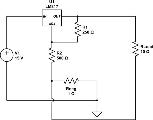
For an electronically regulated supply, it is possible to force output resistance past zero into negative resistance region. This is done by routing some of the load current so that regulating voltage node is adjusted in such a direction that output voltage is forced up. An example of the common LM317 regulator having negative output resistance is shown below - beware, some loads produce wild results:

schematic

simulate this circuit – Schematic created using CircuitLab
Using the built-in circuit simulator, \$ R_{load} \$ was swept from 5 ohms up to 15 ohms:

  • at 5 ohms, voltage drop across Rload is 4.322V

  • at 15 ohms, voltage drop across Rload is 3.993V

The result of that 1-ohm resistor, (and the direction of Rload's current going through it) forces this voltage supply to have negative resistance: at heavier loads, the output voltage goes up. This voltage increase can compensate the voltage drop across the wire resistance.

\$\endgroup\$
3
\$\begingroup\$

Anything that drops in voltage with a rise in current has a negative resistance.

Power sources have this property. The passive components with incremental negative resistance include; any gas discharge bulb or arc, Avalanche effect diodes, Tunnel Diodes, SCR's during trigger phase.

https://en.wikipedia.org/wiki/Negative_resistance

\$\endgroup\$
1
  • \$\begingroup\$ Here is how you can properly measure the negative resistance slope of a Tunnel Diode at any frequency with the proper DC bias and small signal. tinyurl.com/y2qv4g36 \$\endgroup\$
    – D.A.S.
    Commented Nov 23, 2020 at 19:27
3
\$\begingroup\$

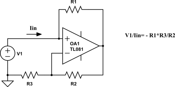
Shown here is a "Typ-A" NIC block. The grounded resistor (impedance) R3 is converted into a negative resistor (impedance) with a conversion factor (-R1/R2). This typ is short-circuit.stable. (An open-circuit stable NIC results for interchanged opamp inputs).

schematic

simulate this circuit – Schematic created using CircuitLab

Comments: The shown NIC is stable as long as the source resistance of the voltage source (not shown in the figure) is smaller than R1. These NIC blocks are use for undamping filters, oscillators and other systems with unwanted positive (parasitic) resistances. Mathematically, they can be treated as "normal" resistors in series and parallel combinations - however, with a negative sign, of course.

A very popular application is the "NIC integrator" (or "Deboo integrator"), where an NIC block is connected to the common node of a simple R-C lowpass. In this case, the NIC can compensate the pos. resistor R - thus resembling a current source which loads the intergating capacitor.

\$\endgroup\$
2
  • \$\begingroup\$ Why did you answer twice? \$\endgroup\$
    – pipe
    Commented Apr 25, 2019 at 17:58
  • 1
    \$\begingroup\$ It was by accident.....I have tried to include the figure (later) - and suddenly there were two answers... \$\endgroup\$
    – LvW
    Commented Apr 25, 2019 at 18:32
1
\$\begingroup\$

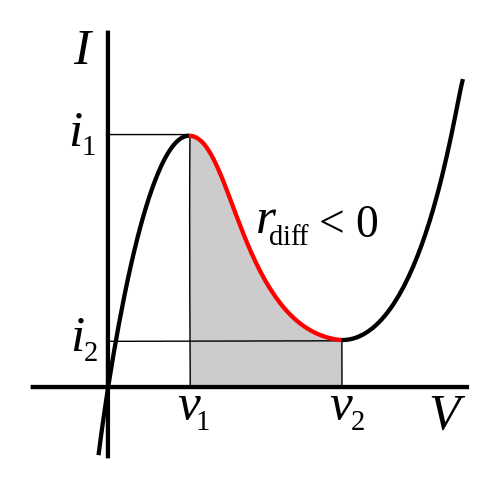
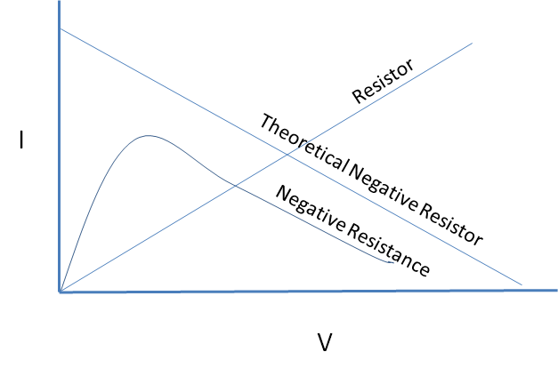
A perfect negative resistor is impossible, but a device can have negative resistance characteristics over a limited range.

The resistance of a non-linear device varies and at a given voltage the equivalent resistance is equal to the slope of the line. If the slope is negative in a range, that range has negative resistance.

enter image description here

\$\endgroup\$
2
  • 1
    \$\begingroup\$ Mattmann944...I think it is important to add that your example concerns a DIFFERENTIAL (dynamic) negative resistance only!! Each working point on your "neg. Resistance" curve resembles a POSITIVE static resistance. More than that, a "perfect" negative resistor is possible, indeed (however, as perfect as each electronic part can be....). No ohmic resistor is "perfect". \$\endgroup\$
    – LvW
    Commented Apr 25, 2019 at 19:25
  • \$\begingroup\$ Yes, your answer is technically more correct than mine. The OP doesn't appear to be a college student, so I tried to keep it simple. I have only seen negative resistance used in the differential sense. Most of the Wikipedia article is devoted to differential. I did say slope, which implies differential. \$\endgroup\$
    – Mattman944
    Commented Apr 25, 2019 at 22:40
1
\$\begingroup\$

Concerning the sentence :

Somewhere I have read that an example of component with negative resistance is a voltage source.

I guess that the "voltage source with a negative resistance" is a crucial missundertanding.

The error is probably the following :

A normal source delivers U = U0 - R I.

If U0 is set to 0 Volts, then the expression becomes U = -R I.

One is tempted to think that the resistor is negative.

In fact, the minus sign comes from the conventions used to describe the sign of the U and I. These conventions are different for sources and passive components

Mostly, and above all in everyday life, this convention is the "Active sign convention" for sources and "passive sign convention" for resistors ( Wiki link )

A lot of people are not aware that they don' t use the same convention when they write U = U0 - RI for a source and U = R I for a resistor

\$\endgroup\$
0
1
\$\begingroup\$

This question has got much attention in 2019 and later. Here's a little more.

Pure negative resistance R=U/I, where U and I are 0Hz DC but have different signs can be simulated with an opamp circuit as already shown by others.

Dynamic negative resistance where U and I only change to different directions in some operating voltage and current zone, but still have same sign can be found as well in many circuits as in components and discharge phenomenons.

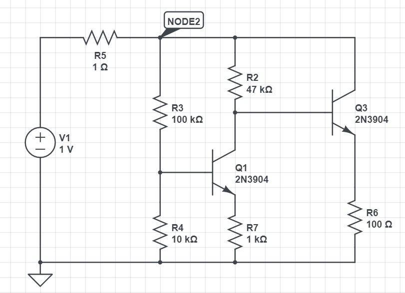
There are two types of dynamic negative resistance. Imagine at first a circuit which takes(like usual resistors) more current as the applied voltage is increased. But the circuit contains some voltage sensitive subcircuit which starts to reduce the taken current if the voltage exceeds a certain treshold. The current reduction is designed to increase more rapidly than the current growth in the main circuit as the voltage grows. An example:
enter image description here

Let V1 be an adjustable voltage source, not static 1 volt only. R1 is an unnecessary part, it could as well be a wire. I inserted it to make easy to plot the current taken from V1, in simulation it's the current of R5. R5=1Ohm doesn't affect substantially the operation.

The plotted graph of the current versus applied voltage is this:
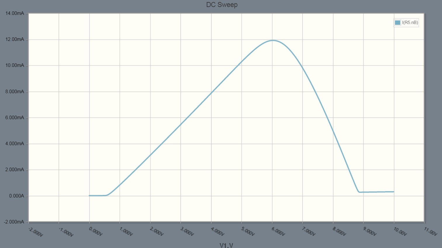
enter image description here

V1 grows upwards from zero. At about 600mV transistor Q3 starts to get so much base current through R2 that there's a growing collector current through Q3. But at about V1=6V transistor Q1 also starts to get remarkable base current. It partially sinks to GND what's coming through R2. The reduction of the base current of Q3 increases steeply as V1 grows. Total taken current decreases from 12 mA to 0,2 mA when V1 grows from 6 to 8,8V. There's average dynamic negative resistance about -240 ohms in voltage range 6...8,8 volts. R5 in series was only 1 Ohm, so its effect is neglible.

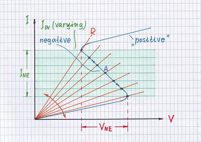
This type of negative resistance is said to be "voltage stable" or as well N-type because I vs U curve a little resembles letter N. It's voltage stable because certain applied voltage causes certain predictable current. But if we knew the current the voltage could be any of three possible values depending on how the current is fed.

BTW. R6 is in principle unnecessary, but it's very useful if you try this circuit. It prevents Q3 to burn.

Diacs, thyristors, UJTs and many gas discharge or avalanche based devices work differently. They have a mechanism which makes more current as the current has reached a certain limit. For example in thin gas thermal collisions and voltage together cause ionization. Ions move due the voltage and cause more ionization due the increased collisions.

The said principle "Current makes more current when the current is high enough" can be easily built into a simple transistor circuit. An example:
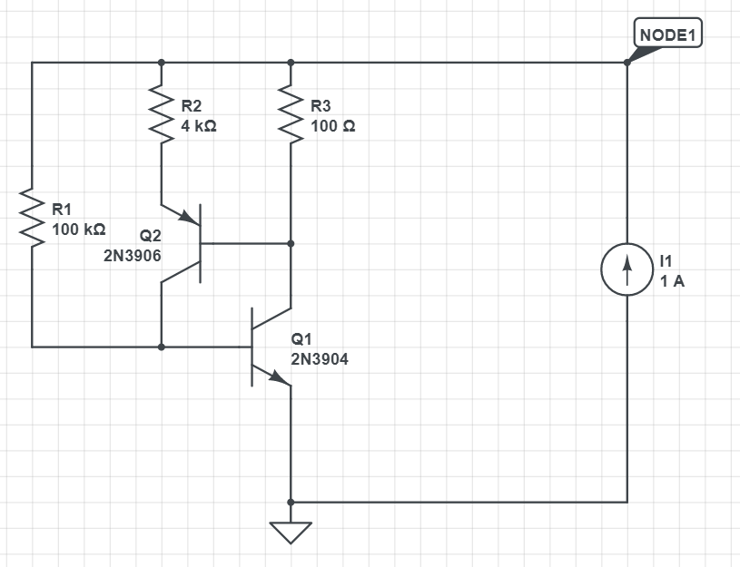
enter image description here

The source in the right is adjustable current source. Feeding with voltage source cannot show the operation properly because the negative resistance is "current stable". But at low Node1 voltage the current would be low, increasing the voltage starts to cause substantial current through R1 at V(Node1)=0,6V thus causing also collector current for Q1.

As the collector current of Q1 increases at some point the voltage over R3 reaches 0,5...0,6V. That makes Q2 conductive and increases the base current of Q1 which causes more Ic and finally more base current to Q1. If we increase V(Node1) gradually upwards from zero we see how the current suddenly jumps upwards. This is actually a flip-flop which flips its state at certain voltage.

As said this is "current stable". By feeding with current source we can reach all possible current values. Here's a current sweep from 0 to 20 mA:
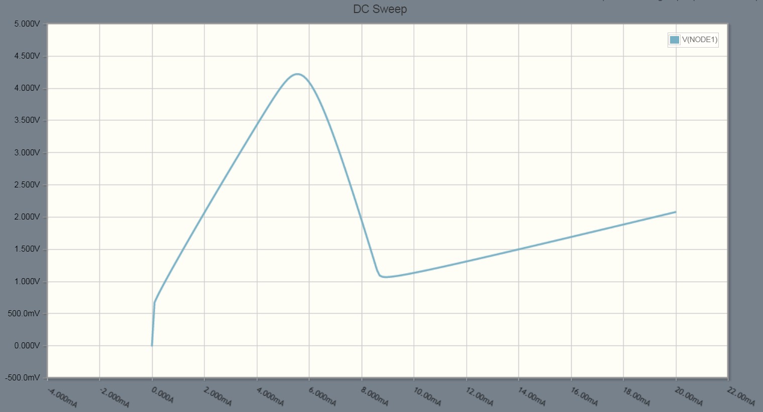
enter image description here

The critical current which would in with voltage fed system make more current is 5,5 mA which needs voltage about 4,2V If we increased the voltage just over 4,2V the current would jump much higher, actually to about 40 mA. That's what can go through R3 with 4V, the transistor needs about 200mV Vce.

If we change the V axis horizontal and I axis vertical in the graph the pattern resembles a lille letter Z. That's another name for this negative resistance type.

About "component with negative resistance is a voltage source"

That's not true. You cannot use a thyristor as a voltage source - something is red or understood wrongly. But a circuit which has negative resistance can output energy which is of course taken from ordinary power supply in practical circuits. We have microwave amplifiers and oscillators based on negative resistance. In lower frequencies ordinary amps are more effective, but in theory nothing prevents us to build a low frequency negative resistance amplifier.

If you only play with equations you can easily put a negative resistor to charge a battery. Simply connect them together.

\$\endgroup\$
14
  • \$\begingroup\$ A great addition with specific circuit implementations to my more philosophical answer! How nice that there are people like you here who deeply understand circuits and reveal the tricks in them! How I just want to have more people like you here... and less like some others... Then SE EE will be a much more attractive place for curious people. Just to ask, "Will it be possible to measure the IV curve of the second circuit if it is powered by a current source?" And yet, "Is not this curve S-shaped (after swapping the axises)?" \$\endgroup\$ Commented Nov 23, 2020 at 18:21
  • \$\begingroup\$ I have used versions of the 2nd circuit only as bi-stable elements. Never tried to measure the U vs I curve with a constant current source.. Practical circuits can oscillate due the reactance - as said: Not tried. There has been an era in Europe when that kind S was too common. Being able to to see this as S can easily be interpreted you like that shape when someone wants to make harm to you. \$\endgroup\$
    – user136077
    Commented Nov 23, 2020 at 18:39
  • \$\begingroup\$ You definitely interested me. Maybe I should browse your contributions; I am sure I will find a lot of wisdom there... "You can easily put a negative resistor to charge a battery" is a very interesting observation. I have illustrated a similar application. If VL is the voltage of a rechargeable battery, it will be charged by 2VL through R. So, the conclusion is that the true negative resistor needs a voltage/current to produce current/voltage. \$\endgroup\$ Commented Nov 23, 2020 at 20:34
  • \$\begingroup\$ Can you reveal something about the drawing tools that you use? Your drawings look very traditionally crafted but they are dense and use as well text, formulas, geometry and colors to present relations. They look look like a single wrong stroke would force to restart with a blank paper. I guess you have somehow worked around it. \$\endgroup\$
    – user136077
    Commented Nov 23, 2020 at 21:09
  • \$\begingroup\$ I will explain all about them... but would you clarify what "They look look like a single wrong stroke would force to restart with a blank paper. I guess you have somehow worked around it." mean. The language barrier prevents me from understanding exactly what you mean... \$\endgroup\$ Commented Nov 23, 2020 at 21:37
0
\$\begingroup\$

In a simple way, resistance is the ratio between voltage and current, if you plot the voltage versus the current present in a certain component, the resistance will appear as the slope between these variables. In a physic way, a positive resistance means that if the voltage of a component rises, the current that flows by also rises, otherwise, a negative resistance means that when the voltage of a component rises, the current declines.

\$\endgroup\$
-1
\$\begingroup\$

DC-DC Converter inputs are a good example of a negative resistance. As voltage goes down, current increases to provide the same power output. Also a negative resistance can be created by an op amp circuit.

\$\endgroup\$

Your Answer

By clicking “Post Your Answer”, you agree to our terms of service and acknowledge you have read our privacy policy.

Not the answer you're looking for? Browse other questions tagged or ask your own question.