6
\$\begingroup\$

A PCB I'm working with has three decoupling capacitors on an IC's Vdd pin - 0.01uF, 0.1uF, and 1uF. They are all in 0402 packages.

I understand that capacitors of multiple sizes are often used because parasitics tend to scale with size, but I was under the impression that this was generally because of different package sizes, not the actual capacitance values themselves.

I also understand that putting multiple capacitors in parallel will increase the overall capacitance while decreasing parasitic values, but I don't see why one would use varying capacitances for that rather than just using the largest value possible for each capacitor.

Is there any reason to use multiple decoupling capacitors with the same package but different capacitance values?

Here's a screenshot of the relevant portion of the circuit schematic (C1, C2, and C3 are all 0402 MLCCs):

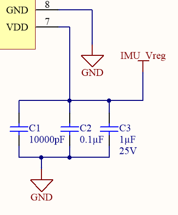
Schematic portion w/ decoupling caps

\$\endgroup\$
5
  • \$\begingroup\$ electronics.stackexchange.com/questions/400683/… seems similar to my question, although it also doesn't have a completely satisfactory answer yet. \$\endgroup\$
    – Darius
    Commented Jun 25, 2019 at 19:48
  • \$\begingroup\$ This is a bad assumption but not the right question. A better question is how does one model and verify the optimal SMPS filter? \$\endgroup\$
    – D.A.S.
    Commented Jun 25, 2019 at 20:45
  • \$\begingroup\$ An example is why are most newbie low ESR cap filter options not the best for a SMPS regulator. tinyurl.com/SMPS-filter Because it was blindly done without filter theory and no Specs !! Try that one on a 1.3MHz regulator. How do you prevent this? \$\endgroup\$
    – D.A.S.
    Commented Jun 25, 2019 at 20:48
  • \$\begingroup\$ Write good specs on spectrum source and load spectrum then design with scattering parameters and choose caps with them and or model each accurately incl. layout ESR, ESL \$\endgroup\$
    – D.A.S.
    Commented Jun 25, 2019 at 21:03
  • \$\begingroup\$ And your next question? \$\endgroup\$
    – D.A.S.
    Commented Jun 25, 2019 at 21:04

4 Answers 4

9
\$\begingroup\$

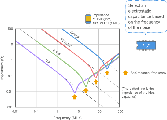
Your initial impression is incorrect. Here is what the impedance of various capacitors in the same package looks like.

impedance

Source

In order to get a sufficiency flat power supply impedance over a wide bandwidth, one needs to use a selection of different capacitors.

\$\endgroup\$
3
  • 4
    \$\begingroup\$ Love that smiley IC. \$\endgroup\$ Commented Jun 25, 2019 at 20:44
  • 4
    \$\begingroup\$ I don't see at all how you can reach that conclusion from your illustration. On the contrary - you can see that the 1 µF capacitor dominates the whole range, and using two in parallel is far superior below 20 MHz, and roughly the same above. The impedance for "smaller" capacitors are only lower in a tiny fraction of the frequency range. \$\endgroup\$
    – pipe
    Commented Jun 26, 2019 at 16:17
  • 2
    \$\begingroup\$ @pipe keep in mind that this is a log scale. At the 100nF resonant frequency the 1uF capacitor has about 2-3 times higher impedance. You use something like 1 1uF, 5 100nF, 25 10nF capacitors. You can achieve the same with 1 + 15 + 75 = 91 1uF capacitors. Look at power integrity (PI) resources for more information. \$\endgroup\$
    – user110971
    Commented Jun 26, 2019 at 18:42
5
\$\begingroup\$

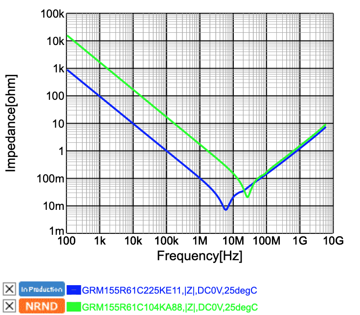
There may be some small benefit. Using a Murata's SimSurfing tool, I graphed the impedance vs. frequency curve for a 2.2uF 0402 (1005 metric) MLCC compared to an 0.1uF one in the same package. The 2.2uF cap is shown in blue in and the 0.1uF in green:

Impedance vs. Frequency for 0402 MLCCs: 2.2uF, 0.1uF

As you can see, the point of resonance is higher in frequency with the 0.1uF, as would be expected of a larger cap with the same parasitic inductance, but, less expectedly, the smaller MLCC achieves a slightly lower impedance between 10 and 40 MHz, at the expense of higher impedance at lower frequencies, as would be expected given the greater capacity of the 2.2uF cap.

So the conclusion is that there's something about the internal structure of the large-valued MLCCs that slightly worsens their high-frequency performance, but below the point of resonance, there seems to be no benefit to the smaller MLCC in a decoupling application.

Of course, the larger capacitor will also have worse performance under DC bias, but generally the larger ones will still end up having a larger effective capacitance under DC bias.

\$\endgroup\$
3
\$\begingroup\$

Indeed there is. The most obvious one is cost. Ceramic capacitors of different values in the same FOOTPRINT (not necessarily package since height may vary) do not cost the same.

Beyond that, ceramic capacitors have different impedance curves (due to the different parasitics as you mentioned) and DC bias curves for each combination of capacitance, dielectric, voltage rating, and package size. It's enough to make your head spin.

From what I've seen, the tendency is that, all else being equal, larger packages have more inductance and therefore hit resonance at lower frequencies, and that squeezing more more capacitance and/or max voltage rating into a smaller package degrades the DC-bias characteristics.

I suggest you go to Murata's SimSurfing website (https://ds.murata.co.jp/simsurfing/mlcc.html?lcid=en-us) and filter out their GRM series capacitors and only look at the X7R capacitors (so you don't get overwhelmed and since effects of dielectric are fairly straightforward). Then compare the "Tech-PDF" of different capacitors where all but one of the parameter voltage, capacitance, and package vary.

I also understand that putting multiple capacitors in parallel will increase the overall capacitance while decreasing parasitic values, but I don't see why one would use varying capacitances for that rather than just using the largest value possible for each capacitor.

Beware...Antiresonance of multiple parallel decoupling capacitors: use same value or multiple values?

\$\endgroup\$
0
\$\begingroup\$

Impedance of capacitor depends on the frequency of the signal passing through. Our job would have been easier had all signals been ideal. But they aren't! There are different frequency components in any signal. In order to selectively filter out the undesired signals, you need different frequency dependent impedances. Hence, different value capacitors!

Check out this video by Dave Jones @EEVBlog https://www.youtube.com/watch?v=BcJ6UdDx1vg To get a visual feel of the concept watch this https://www.youtube.com/watch?v=1xicZF9glH0

\$\endgroup\$

Your Answer

By clicking “Post Your Answer”, you agree to our terms of service and acknowledge you have read our privacy policy.

Not the answer you're looking for? Browse other questions tagged or ask your own question.