2
\$\begingroup\$

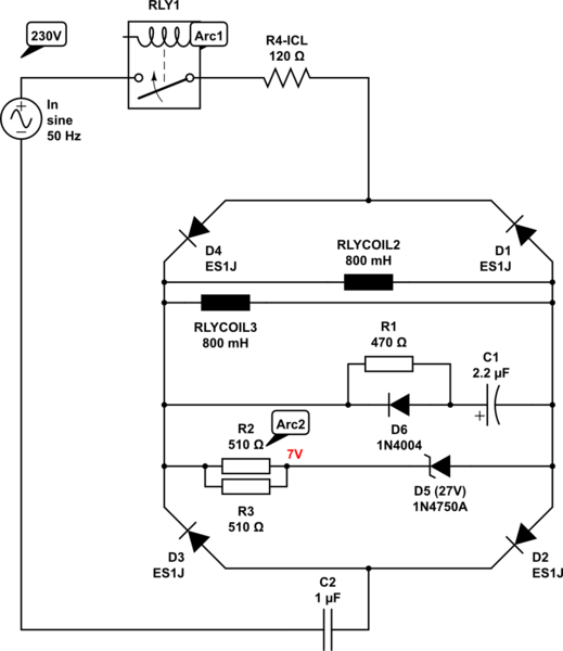
I've got a smoothing capacitor(2,2uF) C1 in parallel with relay coils inside a fullwave diode bridge.

When the circuit is closed through contacts in pre-relay RLY1 it first gives me, almost everytime because of capacitive reactance in circuit (Ce of C1 and C2), an arc over the contacts of the pre-relay, when circuit is closed. But if I place a resistor R1 in front of capacitor C1 to limit the inrush charge current of the smoothing capacitor it will in very short backfire into the resistors R2 & R3 and destroy them. Leading to no zener voltage.

Placing a diode in parallell with resistor R1 for bypassing of the charge current in one direction will end up in almost the same way with destroyed resistors R2 & R3, but not until after almost 1000 tries.

Why is this happening and how can I stabilize the circuit so the smoothing capacitor isn't giving me an arc in either the pre-relay contacts neither backfire into the resistors? Because of C2 there's around 45-50VDC left inside the diode bridge. Any ideas?
schematic

simulate this circuit – Schematic created using CircuitLab

Edit schematic: Added R4, an ICL NTC for inrush current limit.

Second edit:

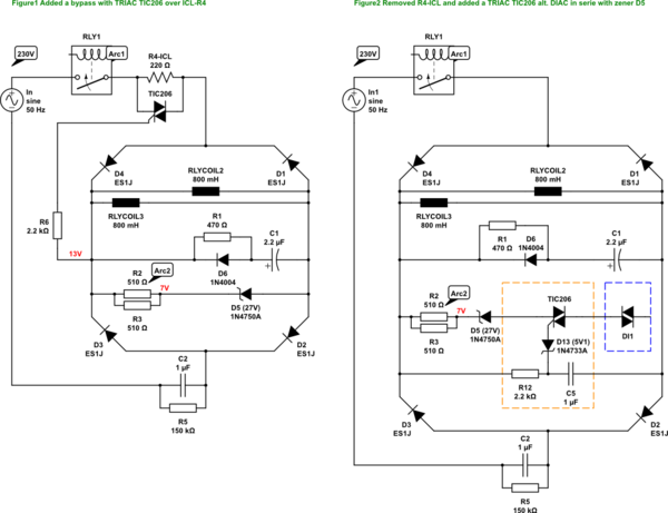
Below answer helped me on the way, thanks! As you pointed out @SpheroPefhany, D6 should be the other way around pointing cathode away(changed in schematics) from smoothing capacitor C1. I've tested some new things to increase the effect over R4(changed to 220Ω) with a TRIAC bypassing(edited as Figure 1) and also found another idea regarding the use of a TRIAC(Figure2 in orange dashed box) or DIAC(in blue dashed box) in series with the zener D5, without the R4 in the circuit. However, to ensure the heat won't destroy the circuit, it needs to switch fast enough to decrease the heat during opening. Is this a working approach or have I missed something?

See updated schematics.
schematic

simulate this circuit

\$\endgroup\$
1
  • 3
    \$\begingroup\$ a smoothingcapacitor(2,2uF) C1 in parallell with relaycoils inside a fullwave diodebrigde witch is in parallell zenered to 27V(zener+resistors R2 & R3 in serie In order to avoid confusion about how things are connected, we EEs use a schematic to show how things are connected. You should include such a schematic as a text leaves to much room for confusion. Use "Edit" to edit your question, then press the icon to draw a schematic. Also, split your text into paragraphs, at this moment it is a "wall of text" and very hard to read (so I don't even read it). \$\endgroup\$ Commented Oct 4, 2019 at 6:55

2 Answers 2

1
\$\begingroup\$

If you happen to apply the power at the positive or negative peak of the mains (325 volts), for an instant more than 300V appears across R2||R3. Your series resistor R1 should probably be in series with the C2 to the mains and C1 connected across the bridge output and no diode D6, unless I'm really misunderstanding what you are trying to do. R1 needs to be an overload-resistant type.

C1 has very low value for smoothing 100Hz to relay coils, and the series 100 ohms means it charges quickly but can't supply much current - maybe your D6 is actually the other way around. I would think something in the 100-470uF would be more like it for C1.

You'll want to calculate C1 ripple (and keep that low enough the zener regulates, assuming that voltage is used for something).

\$\endgroup\$
3
  • \$\begingroup\$ Missed to add at first that I have an ICL NTC resistor before the bridge which will do the same as you hinted above, it can withstand 50J according to datasheet. \$\endgroup\$
    – deel
    Commented Oct 4, 2019 at 9:42
  • \$\begingroup\$ MY intention is to get rid of the arc which appears at the RLY1-contact at closed circuit, which I can accomplish by placing R1 infront of C1 as above, however I then get a huge energy in R2 & R3. When increasing R1 to around 1kohms I see an arc sometimes, but very much less often. Yes, the zenervoltage is to maintain a stable and harmful voltage to the relaycoil to make them live longer. \$\endgroup\$
    – deel
    Commented Oct 4, 2019 at 9:54
  • \$\begingroup\$ Sorry, of course I mean "harmless voltage". C1 is smoothing good enough as it is atm. I would like to avoid increasing it to a higher value, if possible. But maybe its needed after all. D6 are supposed to bypass the limiting of current so the smoothing works as before R1 was added, since R1 are only there to limit the charging current. R4 (ICL) are ment to limit the whole circuit inrush current(including charging of C2). \$\endgroup\$
    – deel
    Commented Oct 4, 2019 at 10:15
0
\$\begingroup\$

The Voltage on C2 is a big problem here. C2 stores significant energy. This causes arc on RLY1. Consider bleeding C2 with a parallel resister of say 150K ohm 2 Watt. Increasing R4 will waste more power but reduce peak currents helping the arc problem. If you wire your relay coils in series then your current needs are halved meaning that C2 could be 470nF and the Zener volts would be doubled. All this will help arc 2 also.

\$\endgroup\$

Your Answer

By clicking “Post Your Answer”, you agree to our terms of service and acknowledge you have read our privacy policy.

Not the answer you're looking for? Browse other questions tagged or ask your own question.