General Comments
To be completely safe, you should probably limit the continuous current to about \$40\:\text{mA}\$. But if you are using this in some kind of pulsed mode, then of course feel free to go higher.
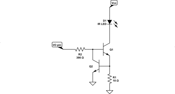
Let's assume you want to operate the IR LED at some current called \$I_\text{LED}\$. (I don't care what value you assign, for now.) Then you can use something along the lines of the following schematic:

simulate this circuit – Schematic created using CircuitLab
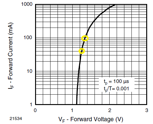
\$3.0\:\text{V} \le V_\text{CC}\le 3.6\:\text{V}\$ from the datasheet I looked at. Your IR LED has a forward voltage that is always low enough (see Fig. 4 on the datasheet) that the above circuit should probably work fine. (Yes, there are extreme cases where the above circuit would be marginal. But I think it is probably fine for most practical uses.)
In this case, adjust \$R_1\$ in order to adjust the current limit you want for the IR LED. As an approximation, try to use about \$R_1\approx \frac{700\:\text{mV}}{I_\text{LED}}\$. I've shown \$10\:\Omega\$ only as an example case. But you should adjust as you feel is appropriate here.
The value of \$R_2\$ has to supply enough recombination current for \$Q_1\$'s base, plus enough excess that \$Q_2\$ can maintain control, too. Assuming a modest \$\beta_1\ge 80\$, we find that \$I_{\text{B}_1}\approx \frac{I_\text{LED}}{\beta_1=80}\$. To be sure that the percent-change of the collector current of \$Q_2\$ doesn't vary too much, we should assume about \$3-4\times\$ that value for the current in \$R_2\$ when the I/O pin is active-high at \$V_\text{CC}\$. If we assume about \$V_{\text{BE}_2}\approx 700\:\text{mV}\$ and \$V_{\text{BE}_1}\approx 900\:\text{mV}\$ (to be generous), then the base voltage at the base of \$Q_1\$ will be about \$1.6\:\text{V}\$. Using the smallest possible value for \$V_\text{CC}\$, that means about \$\ge 1.4\:\text{V}\$ across \$R_2\$.
The actual computation is something like \$R_2\approx \beta_1\cdot \frac{V_\text{CC}-V_{\text{BE}_1}-V_{\text{BE}_2}-V_{\text{IO}_\text{DROP}}}{3\times I_\text{LED}}\$. The value "3" could be as high as "4", instead. But otherwise, that's about how to set it. Also, \$\beta_1\$ can be whatever you feel is likely. \$Q_1\$ will not be saturated (we hope), so the value can often be larger than I suggested above. Meanwhile, the value of \$V_{\text{IO}_\text{DROP}}\$ is the expected drop at the I/O pin due to the required source current. It's likely this value will be under \$200\:\text{mV}\$. (But it may still be useful to take it into account.)
Anyway, something close to the above circuit should be about right. Keep in mind that reducing \$R_1\$ will increase the IR LED current and that increasing \$R_1\$ will reduce the IR LED current.
And the value of \$R_2\$ isn't critical here. So just some close approximation should be fine, if you use generally approximate values in computing its value and finding a nearby standard resistor value.
More Specific
Let's look at Figure 4 from your datasheet:

I've circled two locations in yellow color. This shows that you can typically expect about \$\le 1.3\:\text{V}\$ when driving the LED.
From the following:

You can see that the worst case is \$1.6\:\text{V}\$. So if you do a worst-case design and if you anticipate using as much as \$I_\text{LED}=100\:\text{mA}\$, then that's the worst case voltage. If you add up another \$V_{\text{BE}_2}=700\:\text{mV}\$ and \$V_{\text{BE}_1}=900\:\text{mV}\$ for the BJTs, then you get \$3.2\:\text{V}\$ as the minimum \$V_\text{CC}\$ for the above circuit to work well. Chance are, though, that these values are a bit excessive and that the above circuit does, in fact, meet the minimum \$V_\text{CC}=3.0\:\text{V}\$.
So that is why I'm not really worried much by the circuit I suggested. I think you will be fine with it. But of course, there are some remote possibilities that it start to move into slight saturation. If so, then the \$\beta_1\approx 80\$ is probably a good value to use. This will cover-over this remote possibility, I think. Bottom line is that if you use \$\beta_1=80\$ then I think you will produce a safe, workable design.


