0
\$\begingroup\$

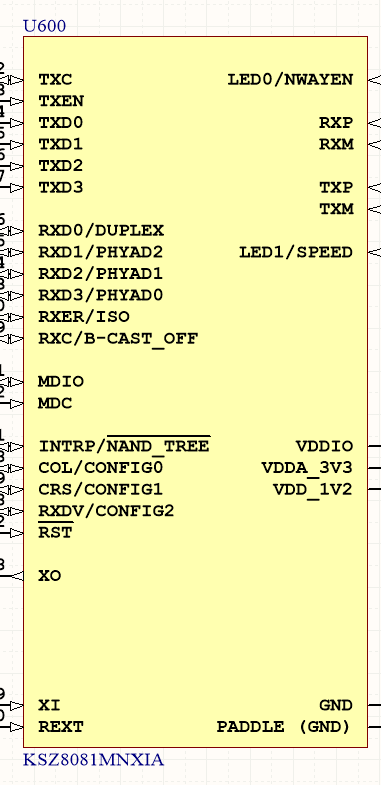
as you can see options strapping pins are multiplexed with RXD# pins .. which are MII interface pins.

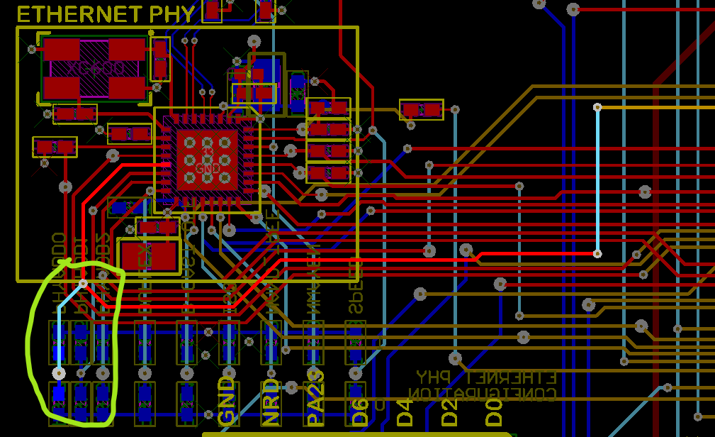
this will make the PCB have "stubs" (connected to MAC + pullup resistors) which is not good in signal integrity wise..

why they didn't build the strapping option on other "non data" pins like LED for example or MDIO .. as much as i know these are just latched at startup of the chip ..

datasheet of PHY chip KSZ8081

enter image description here

stubs im talking about: enter image description here

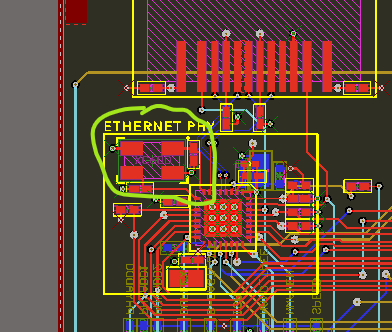
the routing is not mine. its "microchip evaluation board" SAM4E-X-Plained board

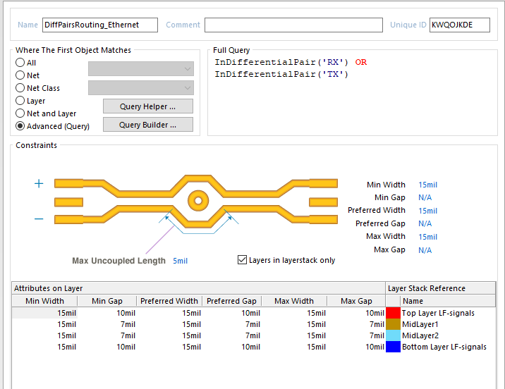
i cant see any rule related to MII only differential ethernet it self which is routed on top and bottom only (layer 6) : enter image description here layer5 is actually power plane (not gnd) i dont know if impedance matching related to it is counted or it must be GND (return path is GND!)..
things originally worried about: (note i didnt put them in the question originally because i thought it will be wide and open) - stubs - layer changing - length matching - impedance matching on non-GND layers - signals crossing overeach other - some are (routed opposite of each other for small length) - clock being near edge of board (how close is near?)

enter image description here

\$\endgroup\$
5
  • \$\begingroup\$ Also, the highlighted line is routed on 3 different layers. Are you actually specifying controlled impedance on all 3 layers? If you aren't then worrying about a 5-8 mm stub at 100 Mbps is kind of silly. \$\endgroup\$
    – The Photon
    Commented Mar 11, 2020 at 15:11
  • \$\begingroup\$ @ThePhoton Given it's a 100M PHY with a MII bus, the MII bus runs at 25 MHz clock. \$\endgroup\$
    – Justme
    Commented Mar 11, 2020 at 15:14
  • \$\begingroup\$ You should edit your question to include that information. Also a link to the PHY chip datasheet so people don't need to go searching for it to answer your question. \$\endgroup\$
    – The Photon
    Commented Mar 11, 2020 at 15:17
  • \$\begingroup\$ But anyway, you've got a 40 ns bit period. Hopefully whatever's driving it doesn't produce rising or falling edges shorter than 4 ns. Corresponding to at least 240 mm wavelength. Any stub of less than 24 mm is unlikely to cause problems. \$\endgroup\$
    – The Photon
    Commented Mar 11, 2020 at 15:19
  • \$\begingroup\$ @ThePhoton i updated the question with my original worries. i was worried of anything i read past few months that doesnt match the board design. i take such boards (from large companies like microchip) as reference design. however, from my researches about signal integrity, EMC/EMI there are various differences that make me worried. i mean even if it doesnt matter (arent these engineers with good industry practices who routed it).. \$\endgroup\$ Commented Mar 12, 2020 at 6:04

1 Answer 1

1
\$\begingroup\$

We can't know why chip designers chose those pins as straps - many other PHYs have them straps too. But you can surely rearrange resistors so that there are no stubs.

\$\endgroup\$
3
  • \$\begingroup\$ rearrange to have shorter stubs you mean? \$\endgroup\$ Commented Mar 11, 2020 at 14:46
  • \$\begingroup\$ @Hasanalattar, yes, shorter stubs. You should be able to reduce the stub to just the thickness of the PCB, plus maybe the size of the resistor pad. \$\endgroup\$
    – The Photon
    Commented Mar 11, 2020 at 15:05
  • \$\begingroup\$ but then you get lot of layer change because of resistors ? or tracks being spreaded with good amount of clearance near resistors ? i know its not differential pair but space/layout tidyness wise ? \$\endgroup\$ Commented Mar 11, 2020 at 17:21

Your Answer

By clicking “Post Your Answer”, you agree to our terms of service and acknowledge you have read our privacy policy.

Not the answer you're looking for? Browse other questions tagged or ask your own question.