2
\$\begingroup\$

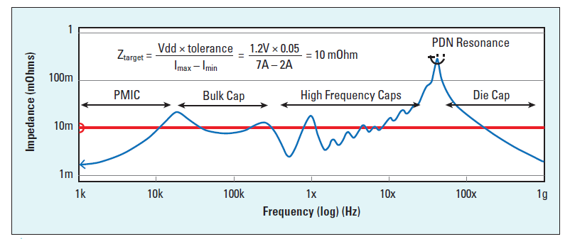
I understand the whole theory behind bypass capacitors, how they are necessary to deliver high-frequency currents to the IC, as the PCB in general has high-inductance, thus high-impedance in high-frequencies. This graph shows the PCB impedance on the frequency-domain, showing how only the bypass capacitors can deliver the MHz currents the IC needs.

PCB Impedance graph

I understand this all on the frequency-domain, but not so much on the time-domain.

If an IC has a high-frequency I/O operation, switching from 5V to 0V, this current will come from the bypass capacitor, but as soon as the bypass capacitor starts to deplete, the circuit will try to recharge it.

The problem is, since all other parts of the circuit (bulk capacitors, VRM, etc) can't respond to such a higher-frequency, then how will the capacitors recharge at all?

As soon as they start to recharge, the IC will try to deplete them again and again.

An analogy I can think of is as if the bypass capacitors are a bucket full of water, the IC is a drain pipe connected to the bucket and the rest of the circuit (bulk capacitors, VRM and etc.) are a dripping faucet, trying to fill the bucket.

The dripping faucet will never be able to keep the bucket filled, as it can't fill the bucket as fast as the drain pipe is pulling water from it.

\$\endgroup\$
7
  • \$\begingroup\$ analogy is wrong. the drain pipe is only fully open a small fraction of the time and can open and close very rapidly. the dripping faucet is actually another drain pipe whose valve opens and closes more slowly \$\endgroup\$
    – DKNguyen
    Commented Apr 19, 2020 at 2:26
  • \$\begingroup\$ But if it can refil the bypass capacitors, then why can't it just provide the IC it's current directly? \$\endgroup\$
    – mFeinstein
    Commented Apr 19, 2020 at 2:27
  • \$\begingroup\$ because demand changes rapidly. it is not flow rate that is the problem. it is changing flow rate to match demand that is the problem. if you have a hundred gallons of water already on the move but you suddenly only need one gallon, what happens if you just try to stop the inertia of 99 gallons from flowing by putting up a wall? likewise what happens if you had 1 gallon but suddenly need 99 gallons? you have to suddenly get the mass of all that water moving \$\endgroup\$
    – DKNguyen
    Commented Apr 19, 2020 at 2:33
  • 1
    \$\begingroup\$ Bypass capacitors compensate for wire inductance -- to model wire inductance, think of the 'water pipe' analogy but the pipes are full of honey or high-viscosity oil, instead of water. Now when the valve opens there is significant delay as flow ramps up, and when vale closes there is significant 'water hammer' pressure increase. This is similar to the voltage transients that the dynamic load currents have due to the inductance of the pcb traces, IC bond wires, and other parts of the wiring system. \$\endgroup\$
    – MarkU
    Commented Apr 19, 2020 at 2:53
  • \$\begingroup\$ So there's a low-frequency continuous-like current to the bypass capacitors that can recharge them so they can provide the high-frequency currents? \$\endgroup\$
    – mFeinstein
    Commented Apr 19, 2020 at 3:26

3 Answers 3

3
\$\begingroup\$

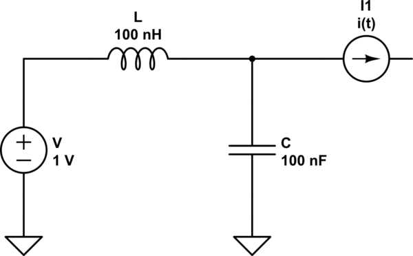
Consider a simple LC model of the power network wherein a time dependent current source represents the IC current drawn from the bypass capacitor \$C\$ with \$L\$ being the power plane inductance to the capacitor.

schematic

simulate this circuit – Schematic created using CircuitLab

As the high frequency current \$i(t)\$ is drawn the capacitor will discharge. However, the power supply will then charge the capacitor through the inductor \$L\$. The inductance prevents the current from changing rapidly, so the capacitor's voltage will drop a certain amount. Eventually the inductor current will increase enough to start charging the capacitor. Although \$i(t)\$ is discharging the capacitor at high frequency, as long as the average current through the inductor is larger, the capacitor will charge.

The capacitor voltage will not be completely stable. It will drop when \$i(t)\$ is large, but as \$i(t)\$ decreases the inductor current will charge it back to its maximum value. So you get a small oscillation at the bypass capacitor. However, as long as the voltage does not drop below the operating range of the IC that won't be a problem.

\$\endgroup\$
2
  • \$\begingroup\$ Good point... But is it correct to say that the average current in the inductor will be larger than i(t)? This sounds like you are creating more current than the circuit is actually consuming. AFACS, the average current in the inductor will be the same as the average consumption of i(t). \$\endgroup\$
    – mFeinstein
    Commented Apr 19, 2020 at 8:16
  • 1
    \$\begingroup\$ @mFeinstein When things settle, yes. But suppose your MCU, for example, starts some processor intensive activity. Then the average inductor current will be less than i(t) initially. Eventually things will even out. \$\endgroup\$
    – user110971
    Commented Apr 19, 2020 at 8:20
2
\$\begingroup\$

Good question.

Once the smaller capacitors have sagged in voltage, because of charge demands, the inductors will build up in current to what is required by the silicon.

This may take many nanoseconds, because of ringing.

In a busy system, you will measure VDD at the Power Supply, and voltages LOWER than VDD at the down-stream points, which may be along the same trace just milliOhms away.

That (slight) voltage drop in the PCB trace (or IC's bond wire and ondie metallization) is what moves the replacement-charges.

\$\endgroup\$
-1
\$\begingroup\$

If an IC has a high-frequency I/O operation, switching from 5V to 0V, this current will come from the Bypass Capacitor, but as soon as the Bypass Capacitor starts to deplete, the circuit will try to recharge it. The problem is, since all other parts of the circuit (Bulk Caps, VRM, etc) can't respond to such a higher-frequency, then how will the capacitors recharge at all?

I think what you are missing is that high frequencies cannot discharge a capacitor since an AC current does not transfer net charge. Only DC can drain a capacitor, so the DC current from that load (once it's on) starts to drain the capacitor, but it's refilled by DC coming from the power lines.

What the capacitor actually does is shunt the AC frequencies to ground so that they don't cause the voltage to transiently drop below spec. If you want to think about it in the time domain, ignore the DC part and just imagine a pulse leaving the power pin. It enters the cap, passes through and then leaves without changing the charge present.

Of course capacitors discharge in AC, they go from +- to 0 to - + back to 0 then again to +- in an AC symmetric signal, so it's charged and discharged back and forth. ... where's this new charge coming from after it was drained by the IC?

An AC signal cannot move charge, so the same charge that was there at the beginning is still there at the end. Hence, the capacitor will not discharge under a pure AC signal. To discharge the capacitor, a DC current must be present.

The confusion here is that you're thinking about a high frequency current (which the power lines cannot pass) but ascribing to it properties of a DC signal (that it discharges the capacitor). This is contradictory. Do you want to discharge the capacitor? Than there must be DC, which means the power lines can respond to that. Do you want the power lines not to respond? Then you cannot discharge the capacitor, only bypass through it.

In reality, what actually comes out of the IC is both high and low frequencies. The low frequency DC signal discharges the capacitor but is low frequency so that the power line can respond by providing more charge. The high frequency signal pass through the capacitor without discharging it and gets shunted to ground.

\$\endgroup\$
6
  • \$\begingroup\$ Of course capacitors discharge in AC, they go from +- to 0 to - + back to 0 then again to +- in an AC symmetric signal, so it's charged and discharged back and forth. I don't mean discharging for good, just being able to replenish its source after providing the current to the IC. \$\endgroup\$
    – mFeinstein
    Commented Apr 19, 2020 at 5:46
  • \$\begingroup\$ @mFeinstein If you start at +V and end at +V, then you do not have replenish anything because you didn't lose any charge. \$\endgroup\$ Commented Apr 19, 2020 at 5:58
  • \$\begingroup\$ Yes, my point is, where's this new charge coming from after it was drained by the IC? \$\endgroup\$
    – mFeinstein
    Commented Apr 19, 2020 at 6:00
  • \$\begingroup\$ @mFeinstein Edited. \$\endgroup\$ Commented Apr 19, 2020 at 6:21
  • \$\begingroup\$ There no point in saying "low frequency DC", there's no frequency in DC. \$\endgroup\$
    – mFeinstein
    Commented Apr 19, 2020 at 6:24

Your Answer

By clicking “Post Your Answer”, you agree to our terms of service and acknowledge you have read our privacy policy.

Not the answer you're looking for? Browse other questions tagged or ask your own question.