1
\$\begingroup\$

Some datasheets define parasitic/parallel capacitance for a diode. MA4E2532 datasheet even list SPICE Cjpar parameter.

enter image description here

But the LTspice D model lacks this parameter. An inductor L model has Cpar parameter but diodes don't. Am I missing something? Is this parameter has a different name or is it inherently useless to define and model it? When I manually add parallel capacitor to a diode it drastically change the results on high frequency.

\$\endgroup\$
4
  • \$\begingroup\$ Are you sure it's not Cjo (there's also Cjsw, but that's not what you're after)? Even if it isn't, that's what you should use (see the help in LTspice > Circuit Elements > D. Diode, the 2nd table. \$\endgroup\$ Commented Sep 14, 2020 at 17:19
  • \$\begingroup\$ Following through the comment that says "Spice Parameters (Per Diode) are based on the MA4E2502 Series datasheet.", and then the application note associated with that device, I'm still confused. Their model doesn't have an "Cjpar" component. I'd say this one is worth a call to a Macom apps engineer. \$\endgroup\$
    – The Photon
    Commented Sep 14, 2020 at 17:37
  • \$\begingroup\$ @aconcernedcitizen Cjo is a different parameter which is also listed in a different column in the table. Cjsw is described as a Sidewall Cjo, is it the other name for Cjpar parameter in the table from datasheet? \$\endgroup\$
    – ZAB
    Commented Sep 14, 2020 at 20:19
  • \$\begingroup\$ @ZAB It looks like it, but I'm not sure. Don't forget that this happens at GHz or so. While you could simulate even at THz with LTspice, that doesn't mean the results will be accurate, unles the simulator was built for such frequencies. There are lots of apparently counter-intuitive things happening there. One consequence of these is the ability to model the diode with an RLC circuit (for small ranges of signal). I'd say try it and see if it fits what you're searching for. \$\endgroup\$ Commented Sep 15, 2020 at 9:48

2 Answers 2

1
\$\begingroup\$

The capacitance of a diode is a function of the bias. The D model has zero-bias capacitance as a parameter. For example, the OnSemi 1N5819 model has Cjo of 110pF.

Edit:

Schottky junction capacitance is:

Cj = \$\frac{\text{Cjo}}{(1-\text {Vf}/ \text{Vj})^{M}}\$

For the 1N5819 mentioned above, Cjo = 110pF, M = 0.35 and Vj = 1.0 (default).

Modelling the capacitance as a fixed parallel capacitor would be very inaccurate.

For very high frequencies, this is an interesting paper showing modeling of the package parasitics as well.

\$\endgroup\$
3
  • 1
    \$\begingroup\$ Nice find on that paper --- it looks like they're studying a very similar structure to OP's actual device. \$\endgroup\$
    – The Photon
    Commented Sep 14, 2020 at 17:40
  • \$\begingroup\$ So why doesn't LTspice have this parallel capacitance parameter in a diode model like it does for inductor? Do they ignore it on purpose and why the MACOM datasheet listed this parameter in its SPICE model section? The junction capacitance Cjo is also listed in the datasheet of course, as well as Cjpar which LTspice missing. \$\endgroup\$
    – ZAB
    Commented Sep 14, 2020 at 19:50
  • \$\begingroup\$ Your answer is about Cjo again but the OP asks about Cpar. \$\endgroup\$
    – divB
    Commented Sep 15, 2020 at 22:50
1
\$\begingroup\$

It's not very clear in the datasheet (and the extra j typo doesn't help much), but they want you to model the Cpar as an additional fixed capacitor across the diode. My guess is that it's meant to represent the package parasitics. Since this is marketed as a very low capacitance diode, the package has significant effects beyond the Cjo of the metal-semiconductor junction. Anyway, you can either do this manually by explicitly putting an extra 0.09pF capacitor across each instance of the diode...or it might be better to just create the entire model as a subcircuit, like so:

.subckt MA4E2532L-1113 A K
D1 A K diode_base
C1 A K 0.09p
.model diode_base D(Is=26n Rs=12.8 N=1.2 Cjo=0.01p M=0.5 Ikf=14m Vj=80m FC=0.5 BV=5 IBV=10u)
.ends

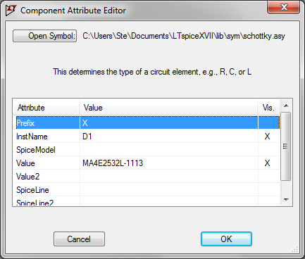
If you use the subcircuit along with one of the standard LTspice diode symbols, don't forget to ctrl-rightclick and change the "Prefix" attribute from D to X, as shown below.

"Prefix" attribute

\$\endgroup\$

Your Answer

By clicking “Post Your Answer”, you agree to our terms of service and acknowledge you have read our privacy policy.

Not the answer you're looking for? Browse other questions tagged or ask your own question.