You're delving into the realm of asynchronous state machines, a tricky but very interesting part of digital logic design. Essentially you need some basic combinatorial logic combined with some asynchronous feedback. If you look at the internal structure of a flip flop (at least the historical method of construction) it's essentially some cross-connected NAND gates with feedback.
The text I used as a reference is by David J. Comer, "Digital Logic and State Machine Design". In the last chapter or two, asynchronous design is covered in detail.
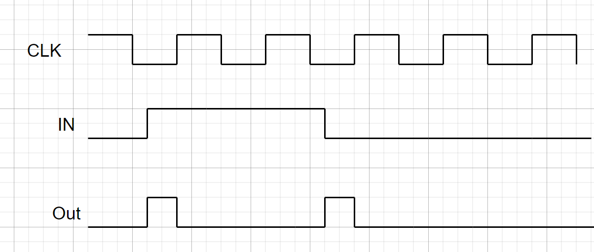
Your waveforms don't specify every possible transition case, so I made a few assumptions about what you want, then came up with this state feedback table, reduced expressions, and a circuit that implements it without any explicit flip-flops.
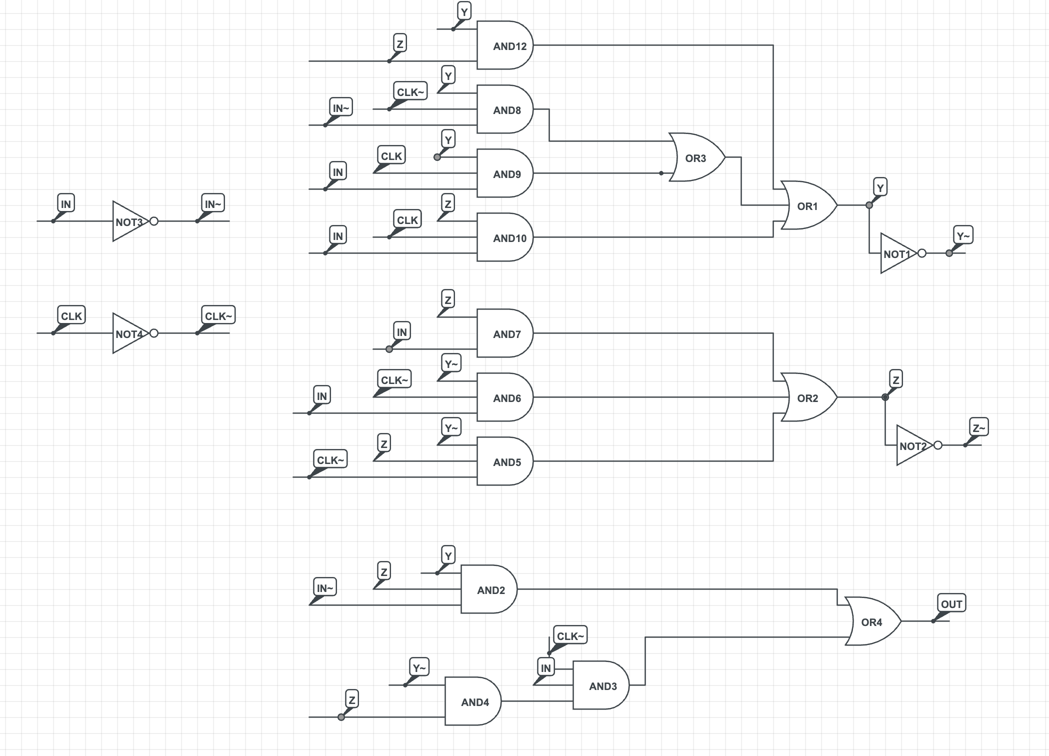
The state table (might need adjustment to change my assumptions):
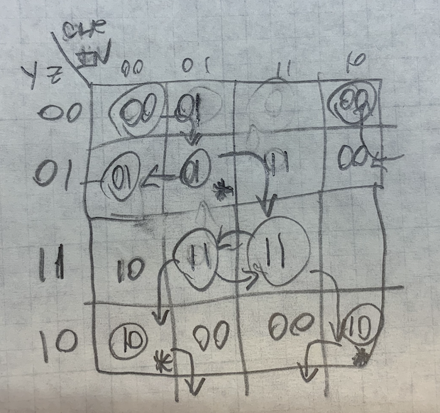
When the value in the cell of the Karnaugh map matches the value on the left side of the table, you are in a "stable state". An asterisk (*) in the table indicates that the output signal should be high in that state. When the value inside the table is different than the value at the left side of the same row, the state is unstable and the state machine will change to the row number indicated inside the state cell. For example, when both signals are low, we start in the top left corner (and YZ also equals 00). When the "IN" signal goes high, we move one cell to the right in the Karnaugh map, where the value of "01" takes us to the second row (where YZ are "01"). Since that cell also contains "01," the state is stable. The asterisk in that cell indicates that the output should be high, and so on.
Apologies for any small errors, I didn't have a chance to simulate the full circuit, but the general approach is valid.
It's this kind of complexity that typically drives us to do fully synchronous design, because it's easier to design and analyze.

