0
\$\begingroup\$

I was thinking why in oscillator circuits with only a DC source the capacitors and inductors don't reach a steady state where the first is an open circuit and the second a short circuit (so the whole thing behaves like a DC circuit).

My hypothesis is as follows: if the transistor were to always maintain a single state (i.e. Forward Active) then indeed the circuit would have reached a simple DC steady state (no oscillations after steady state is reached).

But if the transistors moves between Forward Active to Saturated (for example), there would be 2 DC steady states: one for the FA case, and the other for the Saturated case.

And as the transistor doesn't stay in either condition (FA or Saturated) long enough for the steady state of that condition to take root, the circuit keeps changing its behavior over time.

i.e.

  • FA state associated with DC steady state 1

  • Saturated state associated with DC steady state 2

When the transistor in FA it moves towards DC steady state one, but before 1 is stabilised, Saturation occurs.

At Saturation it moves towards DC steady state two, but before 2 is stabilised, the transistor is forward active again.

(In this example I used, FA and Saturated, but it can go through Cut off as well).

I wonder if this way of thinking is valid? Could people who understand this in depth please comment on the statement above. (I don't mind if it's not the best way to understand oscillators, but I do wonder if as far as it goes, the statement above is valid). Thanks!

(There is a separate question of why a Collpits oscillator, for example, produces a nice sine wave, but my question is more limited - only why it doesn't reach DC steady state regardless of what voltage pattern is produced as it oscillates).

Edits - added examples (click on image to see better):

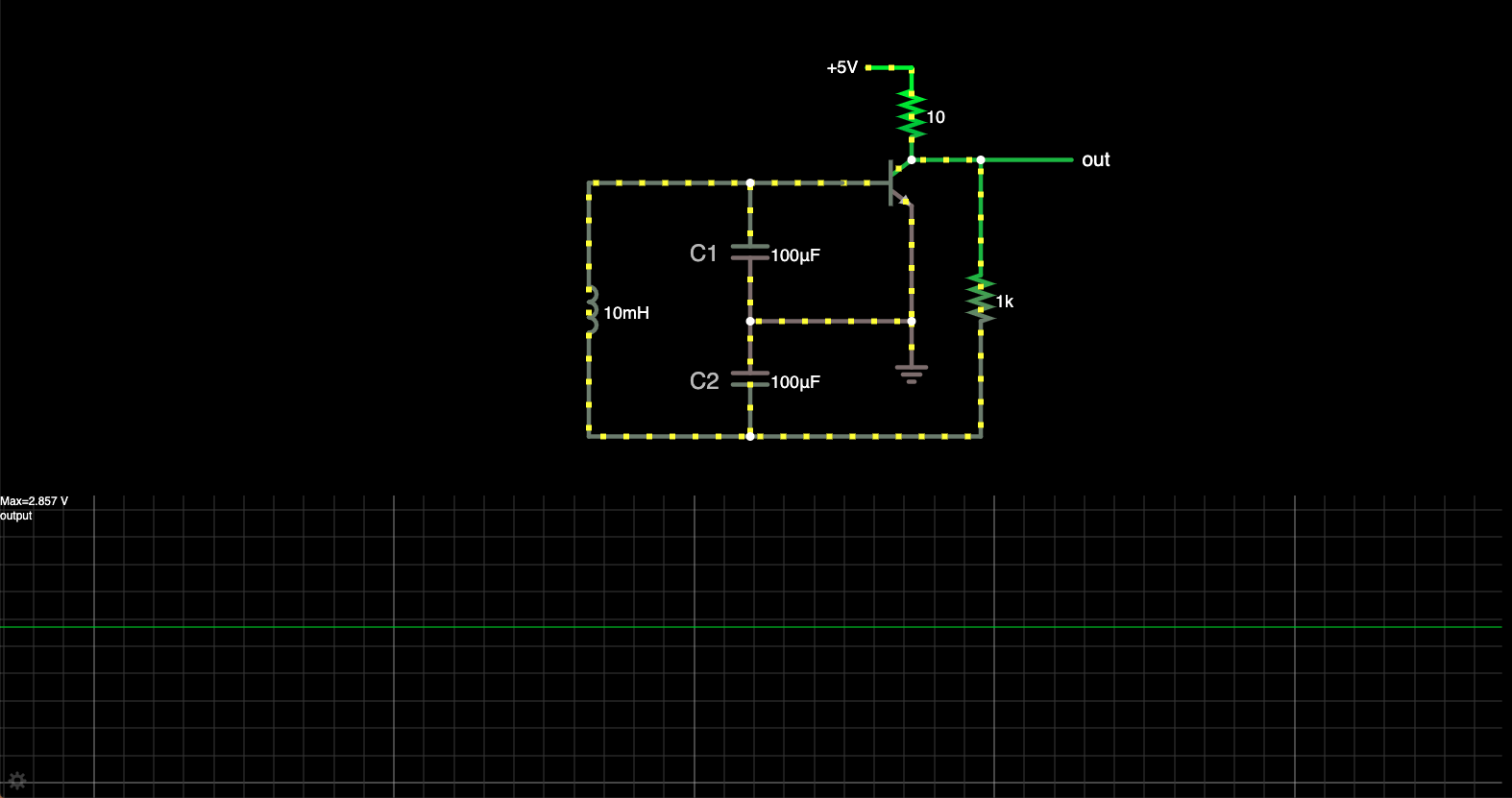
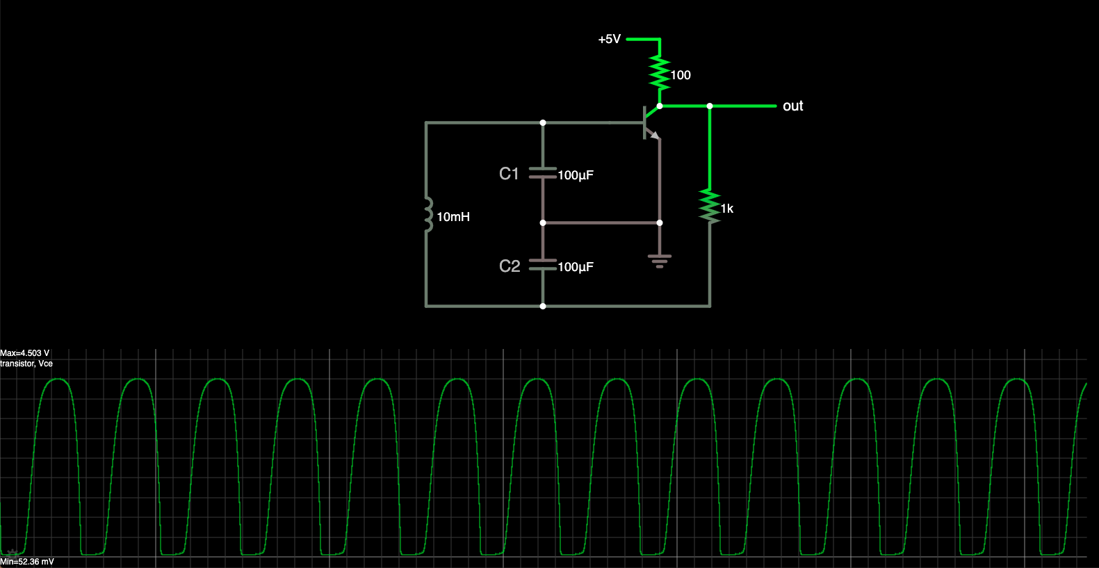
This Collpits type oscillator goes from FA to Saturated:

enter image description here

But having reduced the resistor to 10 ohm, it stays FA, and oscillation no longer occurs (ordinary DC steady state instead):

enter image description here

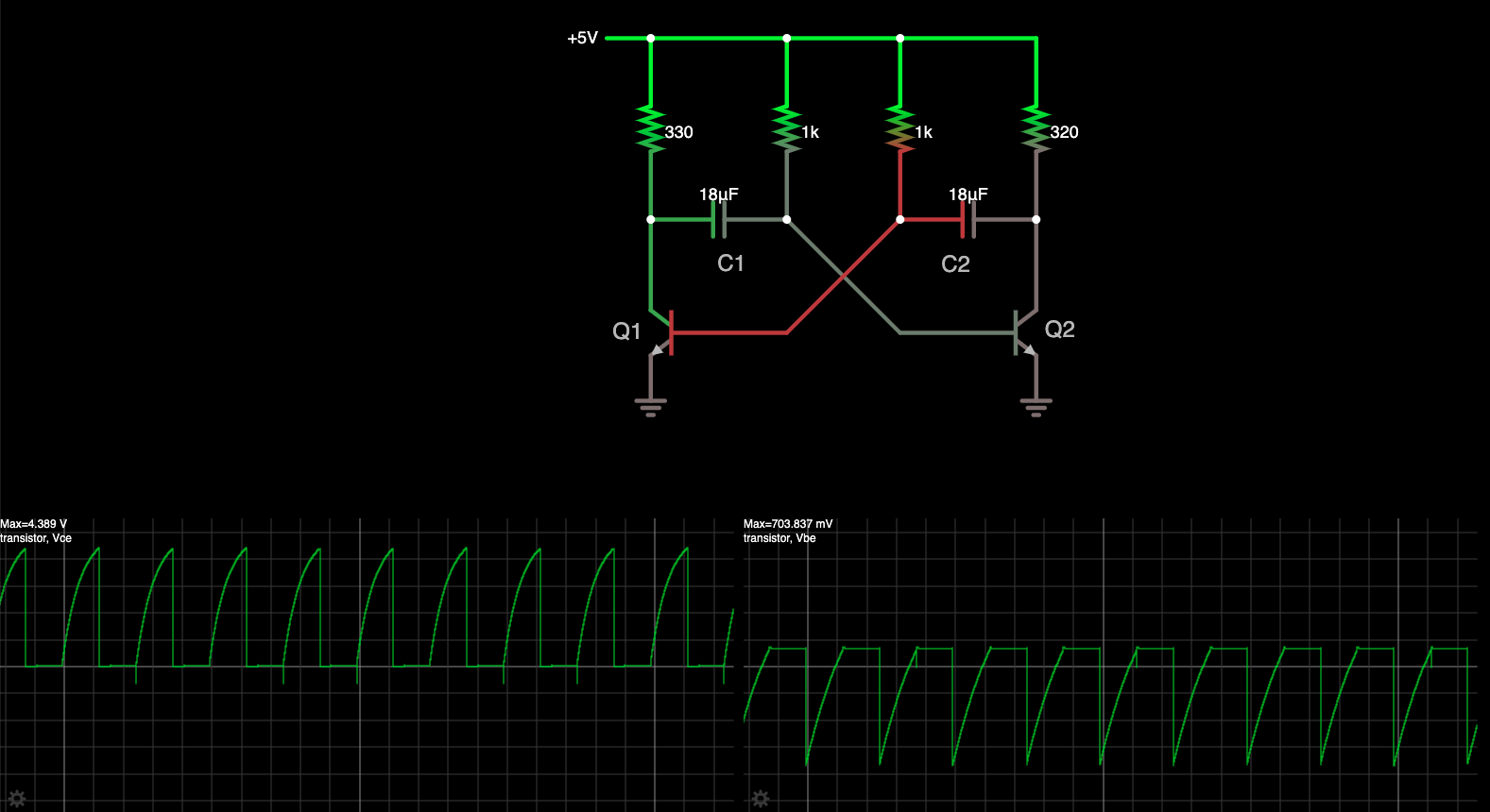
A multivibrator also shifts between mostly Saturated and Cutoff for each transistor:

enter image description here

\$\endgroup\$
9
  • \$\begingroup\$ This is kind of a hand waving argument without a logic diagram, but when an output is saturated, there is no gain but the positive feedback after inversion and phase shift guarantees oscillation if the net loop gain >1. Exactly 1 and you get a sine wave \$\endgroup\$
    – D.A.S.
    Commented Apr 14, 2021 at 23:01
  • 3
    \$\begingroup\$ Daniel, I can show you a phase shift oscillator in which the single BJT is never saturated. It's always in active mode. \$\endgroup\$
    – jonk
    Commented Apr 14, 2021 at 23:13
  • 1
    \$\begingroup\$ @Daniel It most certainly is the case, for example, with the Joule Thief circuit. So yes, saturation can be the reason for oscillation. But it is not the only reason. \$\endgroup\$
    – jonk
    Commented Apr 14, 2021 at 23:29
  • 1
    \$\begingroup\$ @Daniel Well, I'd write something up if I felt I had a sufficiently comprehensive view. But as it is I know only a few things and not everything and this isn't a subject I've exhausted, either. So I'll leave the general topic for someone else far better than a mere hobbyist here to answer. The one thing I can say is that the circuit will use positive feedback in a narrow operational band, but within a circumstance where if it leaves outside that band, other negative feedbacks previously unimportant now become dominant. (For example, the voltage rail limit would certainly count here.) \$\endgroup\$
    – jonk
    Commented Apr 14, 2021 at 23:34
  • 1
    \$\begingroup\$ @Daniel If just left to the voltage rail to deal with, then the circuit will just "rail" and stay there, held stable by the negative feedback of "no more voltage left over to work with." With oscillators it's something else. With inductors, it's usually the fact that the current cannot rise forever and, when it is forced to fall the voltage across it reverses direction. That's the Joule Thief technique. With capacitors, it will often be that the voltage across the capacitor cannot increase any further and this may remove the base recombination current from the BJT, for example. \$\endgroup\$
    – jonk
    Commented Apr 14, 2021 at 23:38

3 Answers 3

4
\$\begingroup\$

The best way to view transistor oscillators is in the frequency domain, rather than trying to apply intuition and imprecise transitions in the time domain. It might make sense for really simple circuits or mechanical systems, but in a typical transistor oscillator there are enough dynamic elements (capacitances and inductances) that ad-hoc hand analysis like that won't necessarily get you far. In fact the journey/derivation I'll present below doesn't consider transistors being in forward active or saturation, and it doesn't even consider transistors at all.

Ultimately, you can view the circuit in front of you as a feedback system. Feedback systems are common and well-understood in electrical engineering -- examples include something as simple as an op-amp amplifier. Generally, we like them to be stable, but oscillators are an example of a feedback network which is intentionally unstable.

In order to discuss how an oscillator can sustain an oscillation, we should start by looking at a stable feedback network first. Here's the stereotypical closed-loop feedback structure, along with an example realization of one. The colors are used to mark corresponding portions of the feedback structure and the example realization I show here.
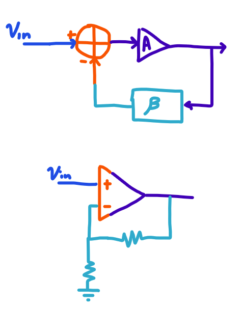
enter image description here

Let's look at the so-called "loop gain" of the structure. To do this, we null the input, and we break the loop at any point. We then inject a signal, let it make a trip around the loop, and see what we get after it goes around once1:
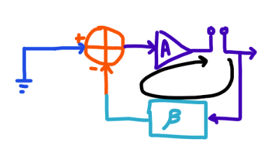
enter image description here

In an ideal world, the loop gain is negative. However, the loop gain is actually dependent on frequency. Under a typical assumption that the circuit is linear and time-invariant, we can consider its response to every frequency of sine wave independently. For each sine wave you put in, you get a sine wave out at the same frequency. This assumption holds really well for small signals, while for larger signals the amplifier may saturate (not necessarily by saturating any individual transistor).

The loop gain is then a function of frequency, and is composed of both a magnitude (how big the output sine wave is, compared to the size of the input sine wave) and phase (how much the output wave is shifted) compared to the input wave. The loop gain tells us all about how our system responds to a sine wave going around the loop, including whether it grows or shrinks. In the definition of loop gain, I consider subtraction a part of it (since it's both in line with the tools I use, and it is conceptually simpler to think about since there's no "double negative" to keep track of at oscillation).

A sine wave that grows (magnitude > 1) while keeping its exact phase (loopgain phase is zero degrees) is going to become an oscillation, and if there's any such frequency at which the amplifier has a loop gain of zero phase, gain > 1, the system will oscillate at that frequency.

Going back to our ideal world where we want a stable amplifier that doesn't oscillate, we want it to have a loop gain whose phase is 180 degrees -- when we put a sine wave deviation into the loop, the amplifier corrects it.

We can plot the gain and the phase using a so-called Bode Plot:
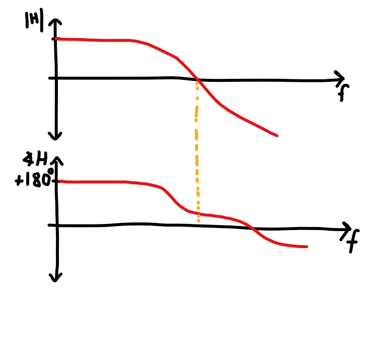
enter image description here

Notice the orange marker and how it indicates an important characteristic of the amplifier circuit: By the point the phase reaches zero degrees (meaning that you put a sine in and it comes out at the exact same phase), the gain is below 0 dB (meaning that the oscillation dies out). This amplifier is stable.

Now consider the same calculation of your Colpitts Oscillator -- it has a structure that is inherently unstable, and its phase reaches zero degrees (meaning that a sine in creates a sine out at the same phase) while the gain is positive -- a full derivation is given in this answer.

In fact, the gain and phase of oscillators can have pretty unusual shapes dissimilar to the smooth and generally downward-sloping plots seen for amplifiers (or amplifiers inadvertenly oscillating due to instability) -- the plot below is from the oscillator I am currently designing for a low-power radio application using a somewhat similar topology and an external resonator to establish the appropriate phase response and resonant behavior at oscillation:
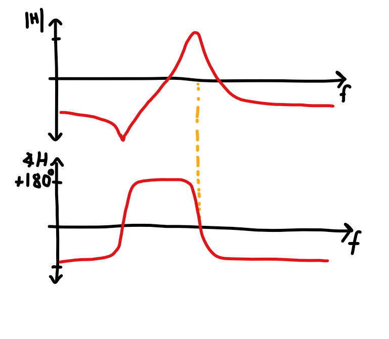
enter image description here

Notice that there are two frequencies where the loop gain phase is zero -- one corresponding to a highly suppressed mode that does not oscillate, and one corresponding to the oscillatory mode at my intended output frequency. The one that does oscillate is the one with the high gain, of course.

This means that you get a sine at the right frequency from anywhere and it'll start building up more and more until it reaches the limits of the circuit's ability to increase further (at which point the "linear" part of our linear time-invariant assumption breaks down and the sine is sustained at the same amplitude without further growth). This is where saturation, and hence gain control, may occur.

Where does that initial sine at the right frequency come from? The thermal noise that's present everywhere in the oscillator contains all possible frequencies, and even the tiniest wisps of energy at the right frequency will build up cycle after cycle, growing until checked by nonlinearities which bring the gain back to unity.

This is of course not the only way to view oscillator topologies. One other topology that's pretty common is the Pierce Oscillator topology used for the oscillator on board microcontrollers such as the Arduino -- it can be seen as an RLC circuit (i.e. a lossy resonator) in parallel with a negative impedance such that the combined result is an RLC circuit with a negative resistance, i.e. a negative loss, i.e. a self-sustaining and growing oscillation.

1 This is a simplification. For maximum accuracy, you have to consider input and output impedances (so you really need to inject both voltages and currents, and test with both open-circuits and short-circuits-to-ground). You also need to consider so-called bilateral feedback: Even though the amplifier "points" in a certain direction, it can pass signals in the reverse direction very slightly.

\$\endgroup\$
11
  • 1
    \$\begingroup\$ I like to mention some errors and contradictions: (1) Three lines above the first BODE-diagram: We want a loop gain of 0 deg (360 deg), NOT 180 deg. (2) We must NOT "break the loop at any point". We must use a node where a small ouput resistance meets a large load resistance. Otherwise, we must mirror the disconnected load. (3) The referenced Colpitt oscillator uses an inverting amplifier. Hence, it is not correct to say "the phase reaches zero degrees". In contrast, the feedback circuit must NOT operate at "resonance". We need -180 deg provided by a 3rd-order lowpass in ladder topology. \$\endgroup\$
    – LvW
    Commented Apr 15, 2021 at 8:49
  • \$\begingroup\$ @nanofarad thanks for the detailed answer. \$\endgroup\$
    – Daniel
    Commented Apr 15, 2021 at 9:50
  • 1
    \$\begingroup\$ @nanofarad and thanks for the effort of drawing diagrams and graphs. \$\endgroup\$
    – Daniel
    Commented Apr 15, 2021 at 9:58
  • 1
    \$\begingroup\$ Daniel, with the exceptions of my small corrections (see my comment) I think the contribution from nanofarad is the best answer to your basic questin. One further comment: The second BODE diagram (with two phase crossings) belongs to an oscillator with a crystal in the feedback loop. This should be mentioned. \$\endgroup\$
    – LvW
    Commented Apr 15, 2021 at 10:04
  • 1
    \$\begingroup\$ Daniel, in your Colpitt circuit it is very easy to see the 3rd-order lowpass in the feedback loop: R-C2-L-C1 in ladder structure. The oscillation frequency results when the phase crosses the -180deg-line (which together with the invereting gain stage gives 360 deg). \$\endgroup\$
    – LvW
    Commented Apr 15, 2021 at 11:07
1
\$\begingroup\$

why in oscillator circuits with only a DC source the capacitors and inductors don't reach a steady state where the first is an open circuit and the second a short circuit (so the whole thing behaves like a DC circuit).

One can certainly design circuits that reach a steady state, where capacitors act like open circuits, and inductors like shorts. However, any circuit, in such a steady, non-oscillating state is, by definition, not a working oscillator.

On the other hand, there is no general answer why oscillators don't behave that way, because there is no general oscillator. There are many different oscillator topologies, and your question does not specify any circuit in particular to analyse.

if the transistor were to always maintain a single state (i.e. Forward Active) then indeed the circuit would have reached a simple DC steady state (no oscillations after steady state is reached).

No, an oscillator does not require leaving the Forward Active mode in order to operate. Rather it is necessary that at some frequency, there is a closed-loop gain of exactly one. This can be achieved in a variety of ways. One method, that is perhaps not so common now is to control gain via an incandescent lamp as a feedback element. As oscillations increase, the lamp heats up, and gain is reduced. Another method is to make use of a diode's non-linear characteristics to achieve gain control.

I do wonder if as far as it goes, the statement above is valid

An oscillator may be designed to use transistor saturation as part of it's overall mechanism. But it is not required that all oscillators behave this way.

why doesn't [a Colpitts oscillator] reach DC steady state regardless of what voltage pattern is produced as it oscillates.

There is a possible state in which a (well designed) Colpitts oscillator could possibly be static. However, this state is meta-stable. That means that although it is static or "stable", it is stable in the same way that a ball balanced on the point of a pyramid might be stable. Even a tiny disturbance will cause the ball to become unstable. Similarly, for the Colpitts oscillator. Any noise (and in electrical circuits, there is always noise), and the oscillator will begin to oscillate. The reason is that the Colpitts oscillator, like many sine wave oscillators, is designed to have a closed loop gain greater than 1 for small oscillations, but that closed loop gain decreases to 1 as the oscillations increase to the designed oscillation amplitude. So, what begins as a very minute oscillation grows and grows until the oscillator reaches a steady oscillation.

[If the Colpitts oscillator is not well designed, it may have difficulty starting up, and require a "kick" to get it started. This would be due to it having insufficient closed loop gain at low amplitudes.]

Once it has begun oscillating, it would never approach the meta-stable state, because any decrease in the oscillation amplitude increases the closed loop gain.

\$\endgroup\$
1
  • \$\begingroup\$ thanks for your answer and addressing directly elements of my question. I've updated the original question with some images by the way. \$\endgroup\$
    – Daniel
    Commented Apr 15, 2021 at 9:54
1
\$\begingroup\$

I think you will understand that transistors are very non-linear amplifiers.

There is no steady current voltage, impedance, current gain or voltage gain.

To get a sine wave you need some method of linearizing the oscillation such as high Q band pass filters or linear RC phase shift network with negative feedback to linearized the non-linear gain.

  • With slightly more complexity you can get simplicity with linear gain using negative feedback by using resistor ratios for feedback/input

  • by soft limiting or a slight reduction in gain you can reduce the square edge to a sine wave.

examples of non-linearity

  • Ic being an exponent of Vbe
  • hFE reduces as Vce approaches Vbe (i.e Vcb=0) to 10 % of max hFE at Vce(sat)
  • there is no linear steady-state in a simple transistor oscillator , It's very non-linear.
  • you describe FA and Saturated as two states but actually it is continuously varying in a single transistor osc.

However with a very high Q ratio it can make current pulses into sine waves with as narrow bandwidth filter in the feedback loop.

This in essence is what Hartley- Colpitts oscillators do.
Convert pulse currents sine wave voltages.

Most of the gain is in the Q of the filter.

Here's one have haven't heard of. Direct coupled differential current pump by Tony.

\$\endgroup\$
3
  • \$\begingroup\$ Thanks for your answer Tony. I've also added some images to the original question. What I found interesting in the link you provided is that the transistors do go between all 3 states (but from the phase shift oscillator example, it's not always the case). \$\endgroup\$
    – Daniel
    Commented Apr 15, 2021 at 9:53
  • \$\begingroup\$ It's nice that you've designed your own oscillator circuit - good stuff. But I've noticed that it does range from FA to Saturation to Cutoff. Would it have worked if the transistors were always in only one state? \$\endgroup\$
    – Daniel
    Commented Apr 15, 2021 at 10:01
  • \$\begingroup\$ Yes of course. My design can be made to balance the Q gain by loading and differential attenuation with Re and a wide variation on hFE to minimize the modulation on Vbe to say 5 to 10% or <50mV This is the reason for modulating Ic and suitable load may prevent saturation with low net gain >1, <2 or <100mVpp out yet exceptional low THD or asymmetric peaks max/min =1.0000. @LvW might appreciate this tinyurl.com/yggz83d2 \$\endgroup\$
    – D.A.S.
    Commented Apr 15, 2021 at 16:20

Your Answer

By clicking “Post Your Answer”, you agree to our terms of service and acknowledge you have read our privacy policy.

Not the answer you're looking for? Browse other questions tagged or ask your own question.