0
\$\begingroup\$

I am designing matching network at 868MHz frequency. I have a source impedance of Z=15.27-j1.27. In order to match that with 50 Ohm, I implemented LC matching network (red color). After that in order to filter second harmonics, I implemented band stop filter (green color). Following that, in order to filter higher order, I implemented CLC filter (purple color). All these are designed for 868MHz frequency.

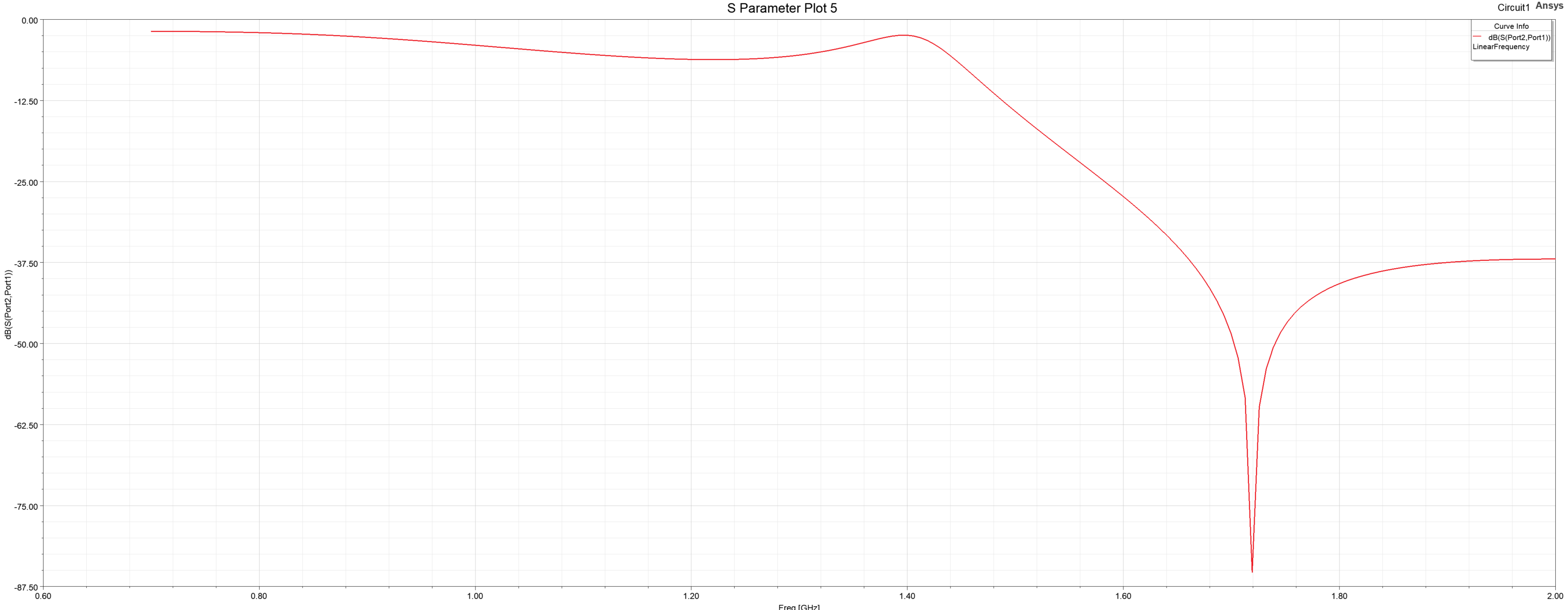
But my problem now is that, when I implemented and analyzed this circuit in Ansys Circuit, I am not getting required output. I have attached my circuit and its result below. Please help me to solve this and correct if there are any mistakes in the component values at the required frequency 868MHz. enter image description here enter image description here enter image description here

\$\endgroup\$
2
  • \$\begingroup\$ What the specs to solve? for s11, s22, s21 ,s12 \$\endgroup\$
    – D.A.S.
    Commented Sep 3, 2021 at 11:54
  • \$\begingroup\$ Your only problem is lack of design specs \$\endgroup\$
    – D.A.S.
    Commented Sep 3, 2021 at 12:09

2 Answers 2

0
\$\begingroup\$

Please help me to solve this and correct if there are any mistakes in the component values at the required frequency 868MHz.

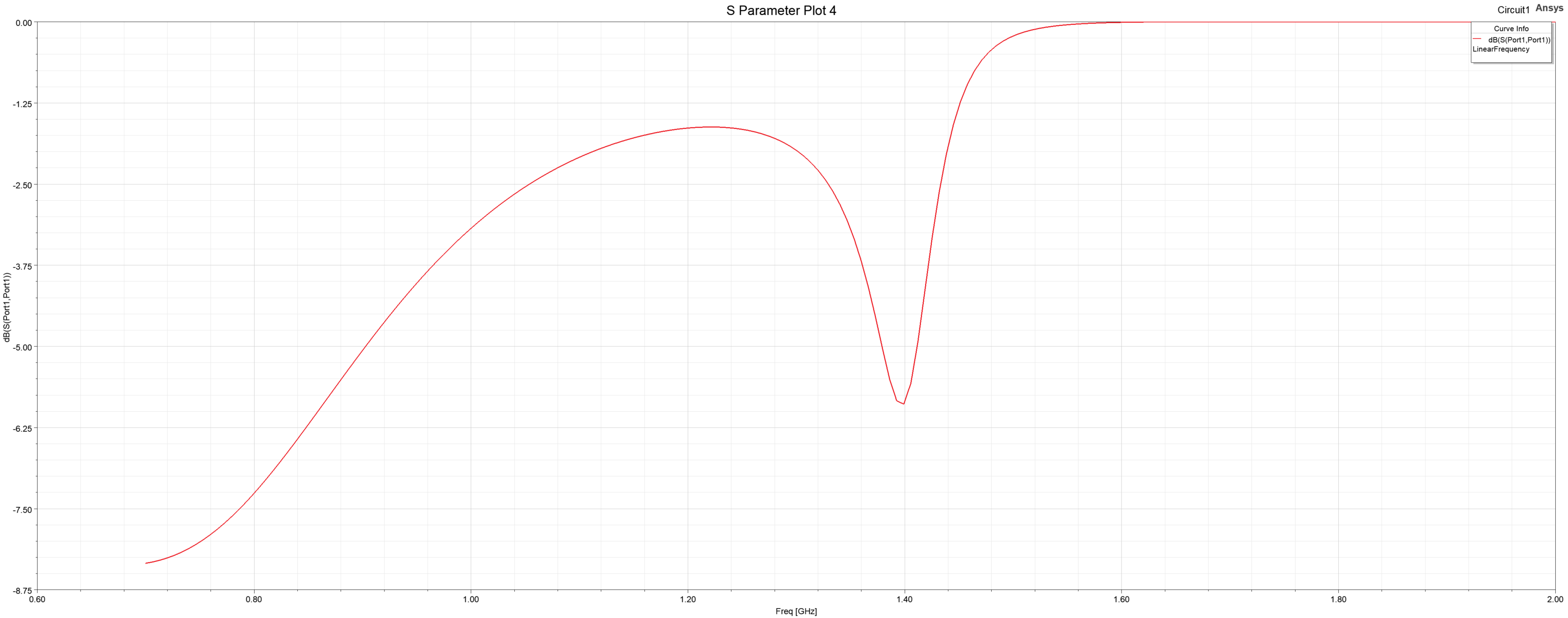
Your 2nd harmonic filter looks likely to be the culprit. I can see that your final stage pi-filter is fine.

My calculator indicates 9.168 nH and 3.6673 pF for the inductor and capacitors in that for 868 MHz with 50 Ω matching but, I suspect that your 2nd harmonic filter is not producing anything like a 50 Ω input and output impedance at 868 MHz and this will ruin the performance of the pi-filter.

Your Z matching network also looks about right (using my calculator) for converting 15 Ω input to 50 Ω .

Concentrate on the band stop filter is my advice and, maybe think about making your final pi-filter cascaded with another to give more high frequency roll-off - see further down the 1st linked page (or just increase the Q of the pi-filter as per changing \$R_X\$ as indicated. Then you can get rid of the band-stop filter quite possibly.

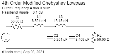
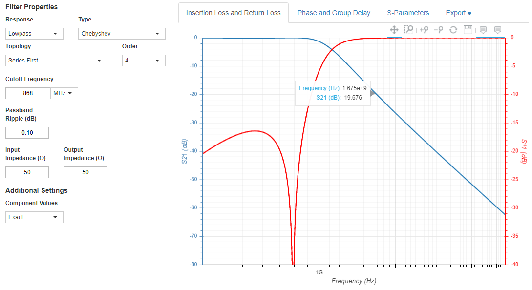
Maybe try this Cauer/Chebyshev filter for the bandstop or the pi and hit both in one go: -

enter image description here

enter image description here

There's about 20 dB attenuation at 1736 MHz.

\$\endgroup\$
4
  • \$\begingroup\$ Yes, I think the band stop filter values are incorrect. I changed those values to 208 pF and 158.8 pH for the band stop filter. Now it looks fine. But I am not sure about these values. \$\endgroup\$
    – Sai
    Commented Sep 3, 2021 at 11:48
  • \$\begingroup\$ @Sai maybe you need to calculate what added complex impedance it inserts at 868 MHz between the matching network and the pi-filter. It still won't look like 50 ohms but the new values will be an improvement.. You should also take the two minute tour to understand what motivates folk to give free help. 208 pH is too small to be practical I suggest. Maybe you should try a cauer filter (see my adds to my answer)... \$\endgroup\$
    – Andy aka
    Commented Sep 3, 2021 at 12:51
  • \$\begingroup\$ Thank you for the suggestion. But when I tried to implement the circuit which you have suggested, the response is similar to the old response. Can you please suggest me to have filter only at 868MHz or with the bandwidth of 10MHz? \$\endgroup\$
    – Sai
    Commented Sep 6, 2021 at 7:55
  • \$\begingroup\$ @Sai I'm really unsure what you refer to. Even if I knew which suggestion you are talking about, I have no idea what you implemented. I made the valid pointer towards the band-stop filter and you made an improvement to it (but you said you were unsure about the values). However, that is the problem area and that is the main focus in my answer. \$\endgroup\$
    – Andy aka
    Commented Sep 6, 2021 at 8:57
0
\$\begingroup\$

Inserting that 2nd-harmonic filter between matching section, and low-pass section is improper design. This network looks like an inductor at the design frequency of 868Mhz.

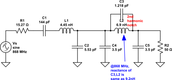
However, if you wish to knock down 2nd harmonic specifically, you can do so by modifying the low-pass filter's inductor to include a parallel capacitor. Doing this will impede the low-pass filter's attenuation in its stop-band (above 868 MHz). So expect that 3rd, 4th, 5th...harmonics will be more visible.
Your inductor L9, currently at 9.2 nH is reduced in value and a small capacitor is added in parallel. At 868 MHz, the parallel combination should be 50.17 ohms (inductive), while at 1736 MHz, the parallel combination is infinite-Z. You may find that component tolerances become tight. The filter network now becomes something like this:

schematic

simulate this circuit – Schematic created using CircuitLab


If the higher-order harmonics have risen to objectionable levels, add another 50-ohm low-pass filter section to this filter's output. It is possible that adding another section may knock down 2nd harmonic enough that C3//L2 (above) could revert back to the original 9.2 nH single inductor.

\$\endgroup\$
2
  • \$\begingroup\$ I tried to implement the circuit which you have suggested. But the response is similar to the plot 5 in the attached picture above. I want to have only 868MHz. Can you please suggest me how can I achieve the design only at 868MHz or with the bandwidth of around 10MHz? \$\endgroup\$
    – Sai
    Commented Sep 6, 2021 at 7:45
  • \$\begingroup\$ You seem now to want a band-pass filter design. Your design spec requires a loaded Q of 87. Filter losses may result in too much attenuation at 868 MHz. unless very low-loss components are used. Helical resonators morph into transmission-line filters at this frequency. Your new design is outside the scope of this question. \$\endgroup\$
    – glen_geek
    Commented Sep 6, 2021 at 15:31

Your Answer

By clicking “Post Your Answer”, you agree to our terms of service and acknowledge you have read our privacy policy.

Not the answer you're looking for? Browse other questions tagged or ask your own question.