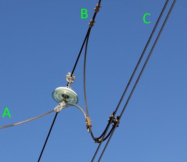
Here goes a view-from-below picture of a 3 kilovolts DC railway catenary

Here B is a suspension cable, C is a two-stranded contact wire - one which the train pantograph touches. Between B and C there's a thick jumper cable that is attached to both B and C. Such jumpers are installed every several dozen meters. Also not shown in the picture but there're hundreds of pieces of thin of wire located every several meters that are attached to the suspension cable, hang down to the contact wire and hold the contact wire at exactly the right height above the rails.
So a lot of effort is made to ensure that B and C have equal voltages at all times.
Now A is a cable that comes from a distribution cable running along the railway. The picture shows how that cable "feeds" energy into the contact wire. Such "feed" points occur about every kilometer.
So the "feed" cable A comes from the distribution cable and is connected to the jumper that is in turn connected to both the suspension cable and the contact wire. Clearly A, B and C will have the same voltage on them.
Finally there's that huge insulator. It separates A from B but both A and B have the same voltage so they could have been connected directly without any kind of insulator.
What's the use of that insulator?
