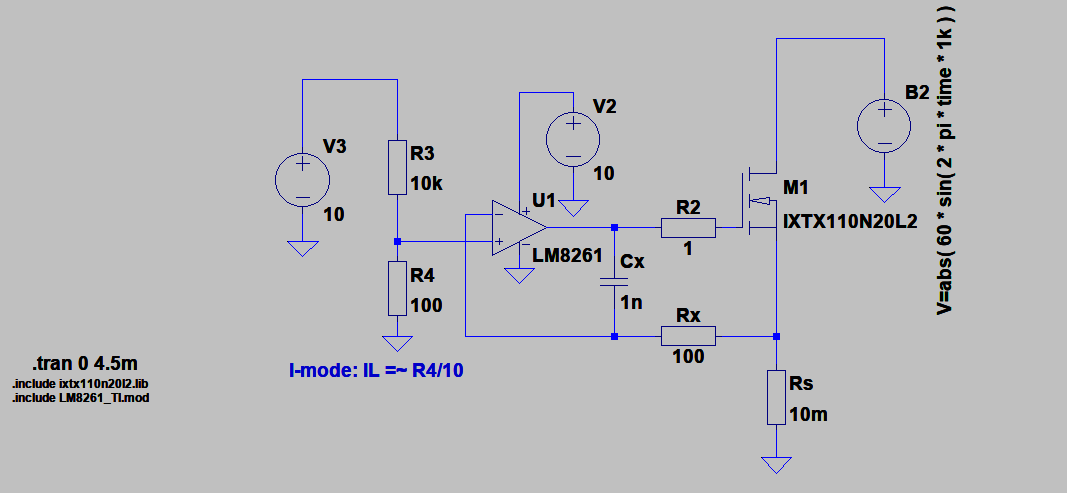
My AC electronic load (previous question here) shall have a constant-current mode. It is being simulated in LTspice.
@devnull helped design the circuit for AC loads, but for simplicity's sake in the context of this question, I have reduced the circuit to one FET and input rectified sine. Additionally, I have tried different op-amps instead of the generic UniversalOpamp2 and replaced the FET with one explicitely designed for linear loads. The voltage divider is set to hold 10A, and the load input is 60Vpp 1kHz.
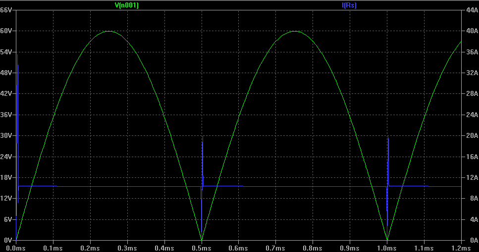
Under these conditions, I am observing current spikes. These spikes are also seen to a lesser extent in constant-resistance mode. As can be seen from the plot below, there's a large spike of 350% during turn-on, and further spikes of 200% for each zero-crossing. It gets considerably worse at higher frequencies.
- Green: Load voltage
- Blue: Load current
Timeline of a spike:
- Load voltage approaches 0V
- Load current falls to 0A
- Op-amp regulates FET to be fully-on
- Load voltage leaves 0V region
- Current spikes due to wide-open FET, before the op-amp can counteract
I am trying to fix these spikes, or at least lessen their amplitude. Whatever I'm doing should work across frequencies of DC up to 20kHz.
Things I have attempted:
- Add an inductor in the load path. 4.7 to 10 μH yields results. But this is a poor solution due to several reasons:
- Induced voltage spikes
- Strong oscillations observed
- The optimal value for the inductor depends on the frequency
- The inductance in the load should be kept to a minimum. Ideally the load should be as resistive as possible (within the bounds of non-linearity due to being constant-current)
Try different op-amps. IXYS linear FETs have high gate capacitance that needs to be charged. The LM8261 selected now, and the alternative LM7322 (both with simulation models from TI) are some of the best. I found the suggestion here. Both their datasheets state they're designed for infinite capacitive loads without oscillations, and they can drive over 50mA. In simulation they end up driving around 25-30mA into the gate (limited by Cx/Rx?).
Tweak Cx and Rx. Doing so will quickly make the op-amp oscillate. Cx ≥ 1n is necessary, even tho it contributes to the delay while regulating out the current spike.
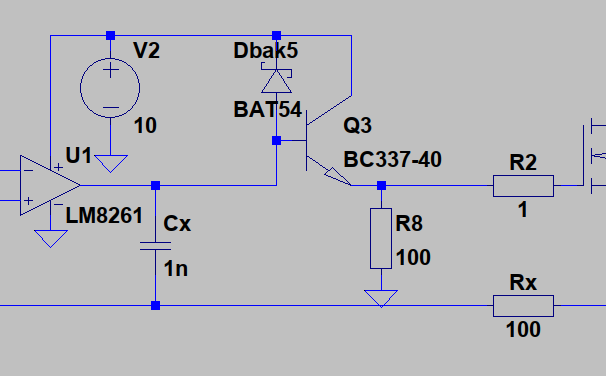
Add an NPN-BJT-based amplifier to drive more current into the gate. It did not end up driving more current.
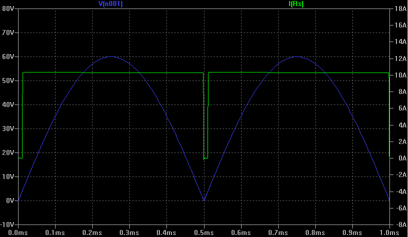
- Detect load voltage and add a dead-time near 0V during which the FET will not conduct. (Near 0V, Q2 stops conducting, making Q1 conduct and send an "override" signal to U1's inverting input)
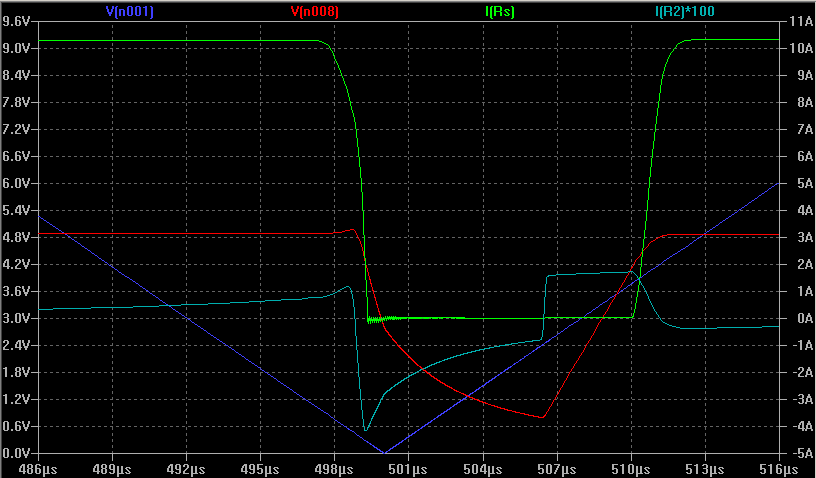
This does work! However, the dead-time lasts much longer than necessary. A small part of that delay is near Q2's base (parasitic capacitance??), but most of it is due to U1 being very slow to recover. Again, Cx seems to be the culprit of that, and its value cannot be lowered due to oscillations. No amount of tweaking the values of other components yielded better results.
- Blue: Load voltage
- Green: Load current
- Red: Voltage at output of U1
- Light blue: Current at output of U1 (multiplied by 100 for visibility)
- Detect load voltage and near 0V, float the FET gate. The idea being, the gate charge would hold the gate voltage until the op-amp is reconnected. Sort of a poor-man's sample-and-hold. This didn't work.
- The voltage of the floating gate is still influenced by what's happening on the drain and source of the FET
- My lack of imagination how something like this could be implemented didn't yield any workable results
All in all, I feel 5. was a good attempt. I just need to speed things up, so that there isn't such a long dead-time. I have spent considerable time trying to do this to no avail.
Any news ideas or improvements to my ideas would be very appreciated. Thank you!

