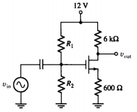
In order to design the circuit you consider two conditions. The first condition is the DC analysis. This is where you are mainly interested in setting the gate voltage so that the drain voltage is roughly at midpoint on the supply. In your example, midpoint is somewhere close to 6V because you have a 12V supply.
Why is it 6V? When you have 6V DC on the drain, and have AC signals superimposed, those ac signals can rise and fall without needlessly crashing into the 12V region or the 0V region i.e. you have designed the DC conditions that are optimum for your ac signal - Getting the DC conditions right is a bit like making a bed properly - you will have a better night's sleep and not roll to one side and crash into the floor!! (I know it's a bad metaphor)
So, the DC is now right - forget about the DC now and concentrate on what the AC has to face. AC, as a decent approximation sees resistors as resistors BUT capacitors as short-circuits - you wouldn't couple your input to an amp through a capacitor that was too high an impedance - there would be no-point so, caps are regarded as short circuits in AC analysis.
The DC conditions are already defined in the DC analysis but the AC signal will see R1 and R2 as AC loads to ground - the power supply is just DC and it can be regarded as a big capacitor so it is shorted. This now means you can calculate the input impedance of the circuit - it's the parallel combination of R1 and R2.
The gain of the amplifier is also defined by the drain and source resistors, Gm of the JFET and the inherent slope of the drain I/V characteristic. I'm not going to go any further because I hope you might be getting the idea. Feel free to ask questions.

