0
\$\begingroup\$

There are many common gate driving circuits, but I think none of them solves my current issue. In my device, I need to slow down the MOSFET a little bit to remove ringing on the switching node, but doing so with a resistor makes Miller capacitance dominant over the gate driver - and then it's a mess.

I am thinking about decoupling the slope forming circuit from the gate. I am going to build something like maybe an RC circuit for the slope and an emitter follower amplifier on the gate.

I have certain concerns about actually slowing down the MOSFET turn on this way - it's not the slope itself, right? It's the current that charges the gate above the threshold. It might happen that the amplifier will simply open the MOSFET up quickly once the threshold is reached.

So the questions are:

  • Is this a valid way to drive a gate?
  • What other ways are there to reliably slow down the MOSFET turn on without getting interference through Miller capacitance?
  • Can I accomplish all that while keeping the timing of the turn on as accurate as possible to allow multiple MOSFETs to simultaneously turn on?

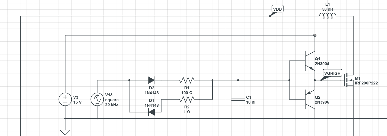
enter image description here

\$\endgroup\$
6
  • 1
    \$\begingroup\$ You can add a capacitor across the gate and the source to slow down the turn-on. If you end up with a too large capacitance then you can place a smaller one across the gate and drain instead (it'll be multiplied by the transconductance and reflect to gate-source). For turning on multiple MOSFETs at the same time, it's not possible because of practical differences coming from manufacturing. Even if you force one to track another for turn-on, thresholds and Q-t behaviours will be different. So the thing depends more on the delay that is acceptable for you. \$\endgroup\$ Commented Oct 21, 2023 at 18:12
  • \$\begingroup\$ Thank you. A simultaneous turn on of course is not possible, but i do want short and predictable events. \$\endgroup\$
    – TQQQ
    Commented Oct 21, 2023 at 18:18
  • \$\begingroup\$ Is your problem related to drain dV/dt or dI/dt? If so, how about some R+C impedance across D-G, or R||L (often a ferrite bead) in series with the source? \$\endgroup\$ Commented Oct 21, 2023 at 18:37
  • \$\begingroup\$ @TimWilliams initial issue was with dV/dt. Capacitor in parallel with the gate is one option, I'll try to find something that work. \$\endgroup\$
    – TQQQ
    Commented Oct 21, 2023 at 19:23
  • \$\begingroup\$ Why is Miller capacitance "a mess"? gate resistance together with Cgd is doing just what are you saying -- controlled dV/dt at the drain. Can you be more specific why simple gate resistance (eventually with additional discrete Cgd) is not what you want? \$\endgroup\$
    – Martin
    Commented Oct 21, 2023 at 22:06

0

Your Answer

By clicking “Post Your Answer”, you agree to our terms of service and acknowledge you have read our privacy policy.

Browse other questions tagged or ask your own question.