I'll treat this as a homework problem, because it's a compact but useful learning experience:
- Try putting a capacitor (with initial condition equal to V1) on each node, to GND. What is the transient behavior? What can we conclude from this about the DC situation in the two cases?
- Or, vary V1 up and down a few volts in the 6-branch case, what do you observe at each node? Does the same failure happen if V1 drops enough?
- What is the Thevenin resistance at the end of the chain? (This can be tested with a IPULSE for example.) What is the incremental resistance of each branch at the operating voltage? Is there any coincidence in parameters at the point where the error occurs?
- What is the nodal analysis of the basic system:
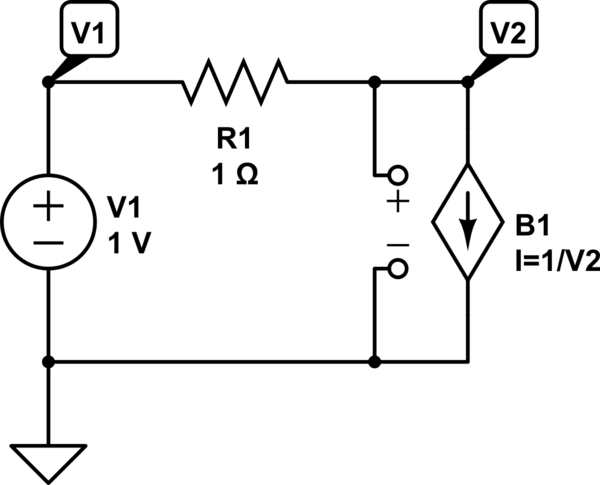
simulate this circuit – Schematic created using CircuitLab
you should be able to solve this easily by hand, including the Thevenin resistance at V2. What happens as V1 decreases from some initial/nominal value?
Mathematically, what this should lead you to is the nature of a singularity, as applied to nodal analysis equations, and also the behavior of negative resistance elements. Notice that you are dividing by the voltage, so response is reciprocal, current is divergent towards zero, and undefined at zero (a singularity).
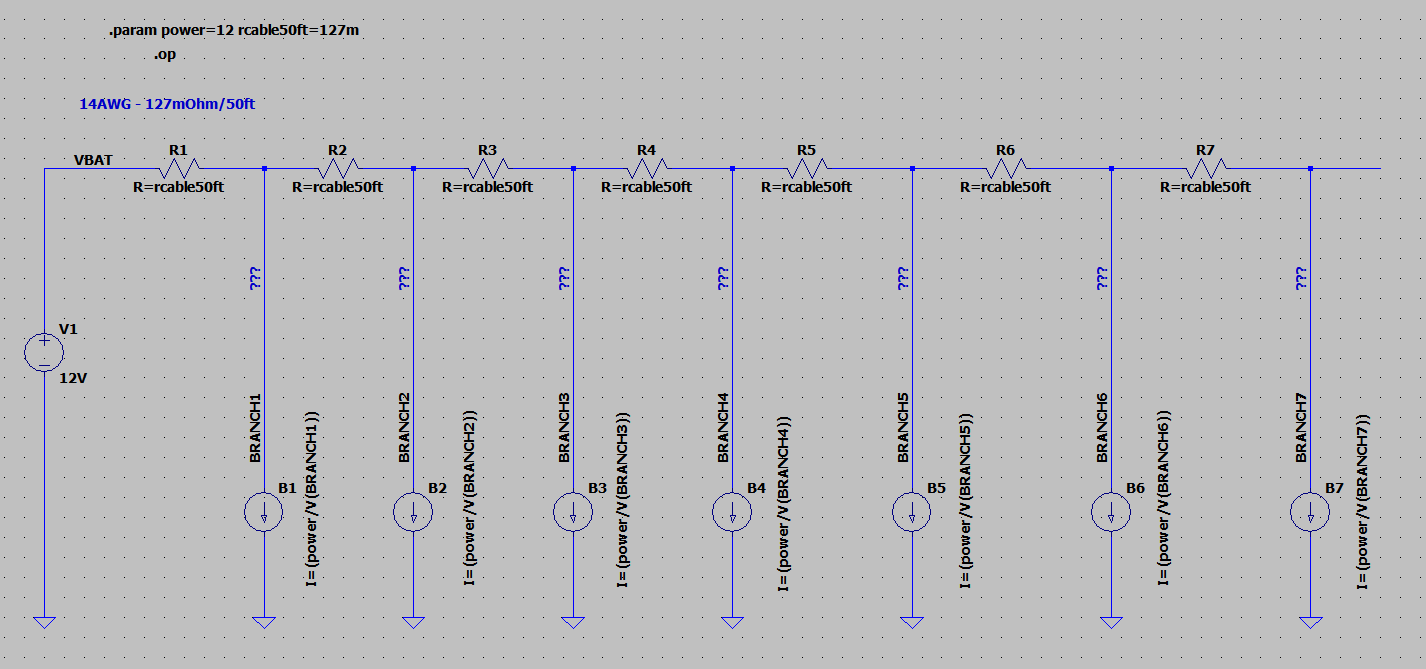


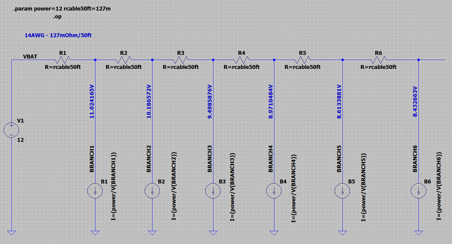

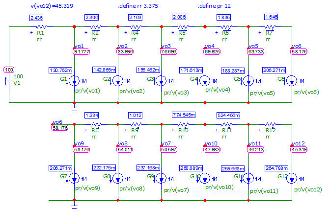
not surprisedwhen simulation problems may arise. There may be more than one stable solution. Not sure why you are finding good results for just one branch. But I don't like the math I see. \$\endgroup\$vprxoverparameter). \$\endgroup\$