1
\$\begingroup\$

I'm new to LTspice and I need to measure all the possible values of the drain current of a JFET when certain combinations of Vds and Vgs values are reached. That is, I need to record specific points of the output curve of the JFET.

For example: Vgs will vary from 0 to -5V in -1V steps; for each Vgs value, Vds will vary from 0 to 10V in 0.5V steps; for each Vds in each Vgs I need to record the drain current.

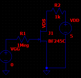
This could be done with nested .step directives if Vds was a voltage source (so I could use a {Vds} param), but I have this circuit instead:

enter image description here

Any idea is welcome.

Thanks in advance.

\$\endgroup\$
5
  • 1
    \$\begingroup\$ First, read up on the .MEAS card. Then play with it. Its results will appear on the View/Spice Error Log menu option. This may be what you want -- not sure, though. But it has a lot of options and a lot of capability. So probably it will help. \$\endgroup\$
    – jonk
    Commented Nov 5, 2020 at 0:40
  • 1
    \$\begingroup\$ What's the purpose of this exercise? If you want to know how the JFET behaves, just remove R2 and apply VDD directly to the drain. \$\endgroup\$
    – The Photon
    Commented Nov 5, 2020 at 3:32
  • 1
    \$\begingroup\$ Sounds like you want the JFET characteristic curves. This is usually done by doing a DC sweep with both of your voltage sources. Like the previous comment stated, remove R2 to acheive this. \$\endgroup\$
    – Ste Kulov
    Commented Nov 5, 2020 at 3:34
  • 1
    \$\begingroup\$ Also see <My Documents>/LTspiceXVII/examples/Educational/IGBT.asc for a way of doing a DC sweep. It's about an IGBT, but it can be used for any transistor. \$\endgroup\$ Commented Nov 5, 2020 at 8:42
  • \$\begingroup\$ @SteKulov, I needed the numeric values from specific points at the characteristic curves. I found a workaround and posted it as a answer. \$\endgroup\$ Commented Nov 25, 2020 at 0:59

1 Answer 1

1
\$\begingroup\$

Here's the closest procedure I've got to the fully automated approach:

I've created a parameter called VGG for the gate voltage source, then I've stepped it throught the desired points:

.step param VGG list 0 -0.5 -1.0 -2.0 -3.0 -4.0 -5.0

Then for each desired Vds value, I've created a corresponding variable Id_ using the .meas:

.meas DC Id_<x> FIND I(R2) WHEN V(VDS)=<value>

As I needed 7 different Vds values, I had to write 7 different .meas lines (thus 7 Id_ variables). But I guess it's better to write 7 lines than writing 49 lines.

\$\endgroup\$
1
  • 1
    \$\begingroup\$ I think you misunderstood why we were asking about R2 in the comments. Based on your answer, it's unnecessary and you should use .meas DC Id_<x> FIND ID(J1) WHEN V(VDS)=<value>. \$\endgroup\$
    – Ste Kulov
    Commented Nov 25, 2020 at 1:16

Your Answer

By clicking “Post Your Answer”, you agree to our terms of service and acknowledge you have read our privacy policy.

Not the answer you're looking for? Browse other questions tagged or ask your own question.