-1
\$\begingroup\$

When I use op-amps in a single-supply limitation, I usually build a virtual ground with the op-amp.

For the simplest case, a buffer consisting of an unbuffered reference voltage, passed through an op-amp. It is also often necessary to drive a capacitor from this buffer. For many op-amps, this causes loop instability.

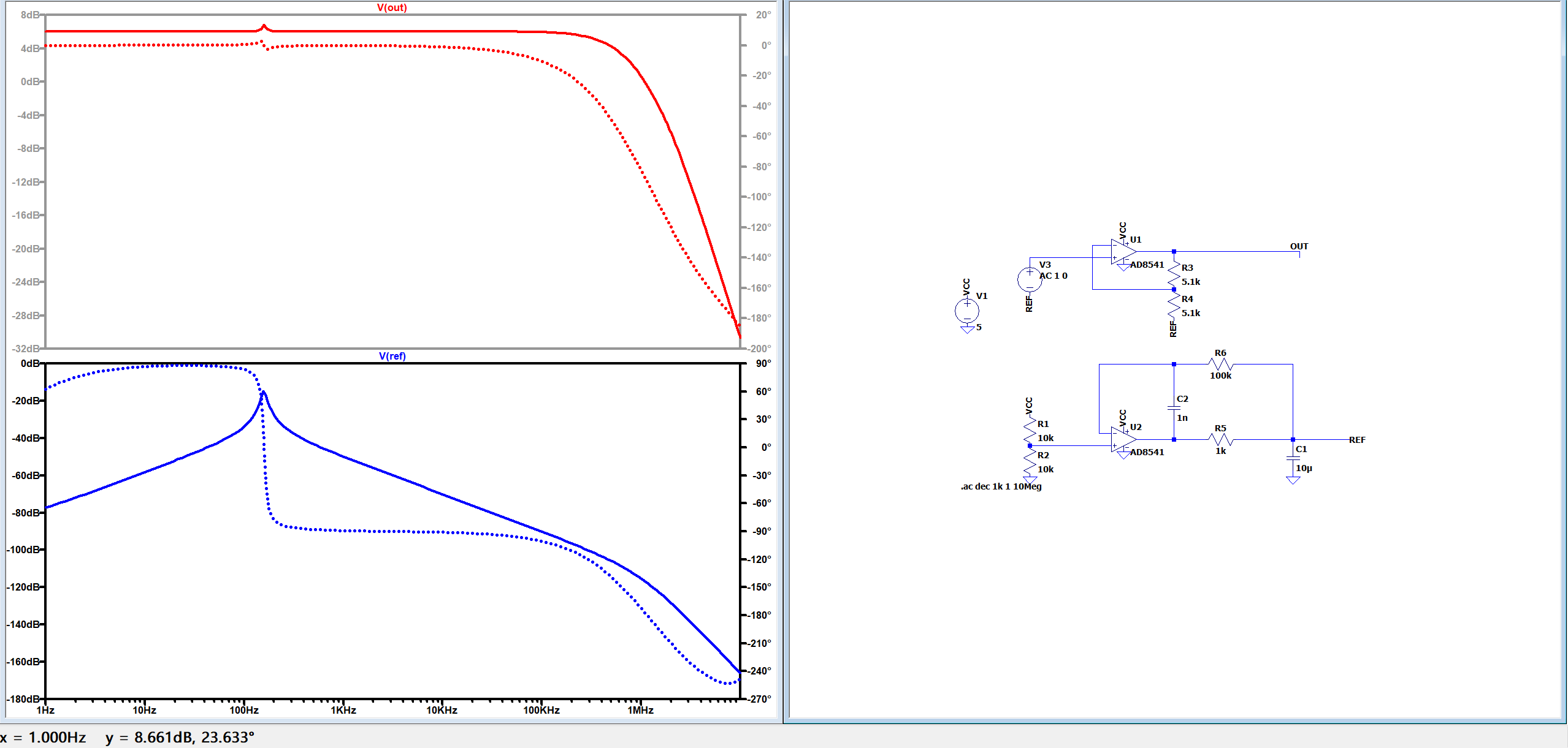
To solve the above problem, it is usually possible to compensate to some extent using a feedback loop as shown below. However, a strange pole is introduced in the frequency response. The figure below exaggerates a situation where a virtually bad frequency response causes other amplifiers using this reference to appear unflat.

circuit example

Under normal conditions, I can adjust this peak to be at least less than -40dB,But it's hard to achieve better compensation. but it is still uncomfortable in broadband high-precision applications.

Is there a better way to build this virtual ground? Or is it more recommended to separate the power rails, build positive and negative supplies, and use a true 0V as the ground plane in demanding applications?

Your advice would be appreciated.

I'm not a native English speaker and apologize in advance for possible inaccurate expressions, if you have questions, please reply and I'll make additional clarifications.

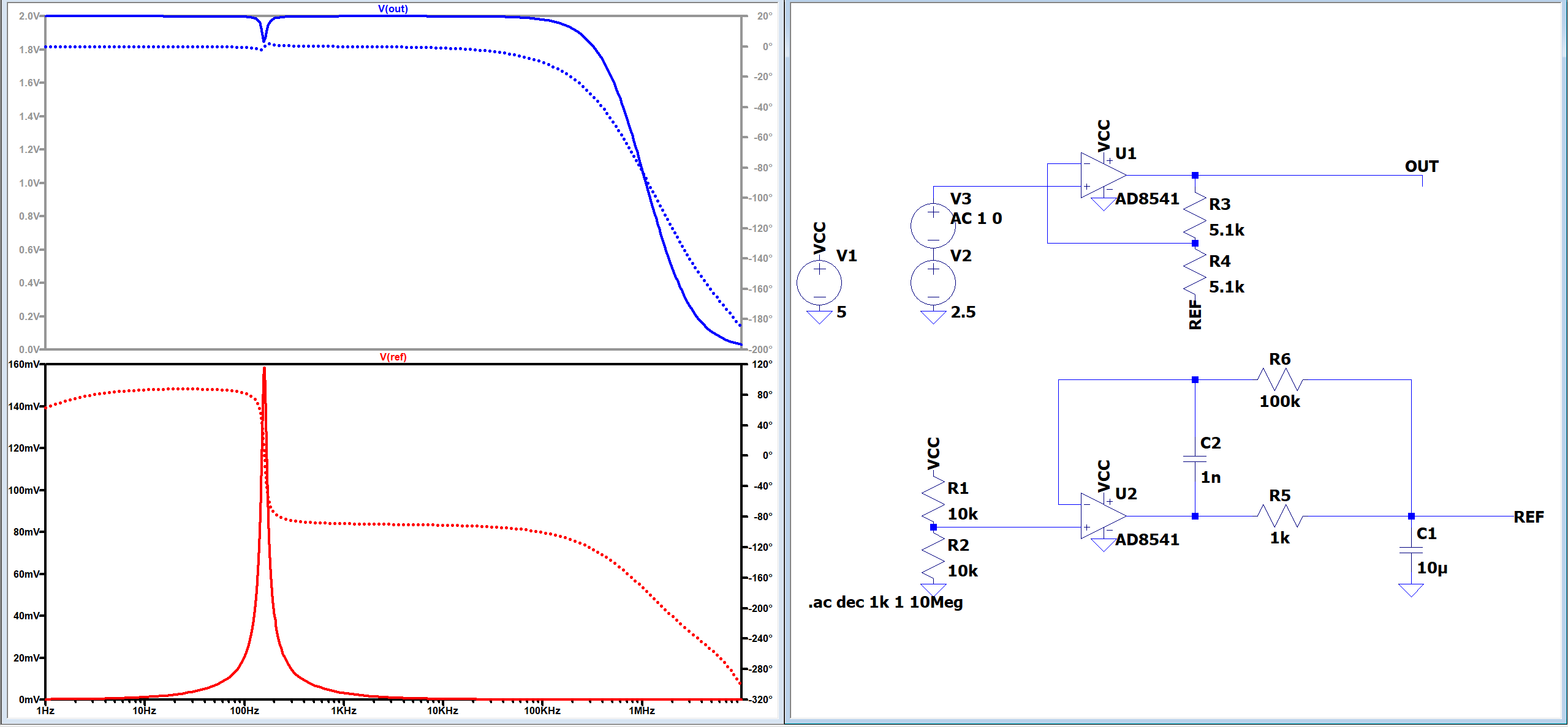
add: use ref instead of V2

Using a fixed value of v2 as a bias is simply to bias the inputs to the operating range of the op-amp,in order to perform AC analysis.

Taking a value of half of VCC is just a arbitrary and is not intended to be associated with Vref. This circuit is used for example only and does not represent actual working conditions.

\$\endgroup\$
4
  • 1
    \$\begingroup\$ Why do you offset your amplifier's input using V2 w.r.t. ground, instead of w.r.t. to REF? Why would you go to all the trouble of producing \$V_{REF}\$, and then not share it? I'd like to see the bode plot with V3 relative to REF. \$\endgroup\$ Commented Dec 13 at 12:36
  • \$\begingroup\$ Thank you, I've added the graphics and some clarifications \$\endgroup\$
    – pigeon CNC
    Commented Dec 13 at 13:31
  • \$\begingroup\$ "This circuit is used for example only and does not represent actual working conditions" Maybe providing more details about them would contribute to receiving more detailed suggestions. \$\endgroup\$
    – MeGrogu
    Commented Dec 13 at 15:41
  • \$\begingroup\$ There is nothing "virtual" about the 2.5 V REF voltage generated by the REF buffer to bias the main amplifier. The in-loop compensation cap C2 (1nF) is too small which makes the buffer, due to the large capacitive load, unstable. The output impedance of the buffer as shown is close to 900 Ohm around 160 Hz. As this impedance is in series with resistor R4 (5.1 k) from the main amplifier, the gain will be off at the mentioned frequency. \$\endgroup\$
    – Raonoke
    Commented Dec 14 at 5:23

3 Answers 3

1
\$\begingroup\$

Modelling of this usually requires opamp models that represent the output stage well. In my experience it's a bit of a crapshoot. I've had designs that measured plenty stable in-circuit but LTspice hated them. Converse has also happened: crickets in LTspice, but on the board it was singing.

If you have some power to spare, stick an follower (NPN or NMOS) on the output of that op-amp, and load it so that has good conductance. Start with 10mA, go down, and see at what point it'll oscillate again. Set up a "tickler" to destabilize the circuit periodically so that oscillations will get induced reliably.

An AD8541 is a slow op-amp and I doubt its output stage is very stiff. Loading those down with a capacitor usually doesn't end well. They just don't have enough oomph.

\$\endgroup\$
3
  • \$\begingroup\$ Can I ask what crickets and singing mean? "crickets in LTspice, but on the board it was singing." \$\endgroup\$
    – jonathanjo
    Commented Dec 13 at 16:59
  • 4
    \$\begingroup\$ @jonathanjo 'Crickets' is slang for silence, as in something is so quiet all you can hear is crickets. 'Singing' means the opposite, making noise. In this context it generally means oscillating. \$\endgroup\$
    – GodJihyo
    Commented Dec 13 at 17:56
  • \$\begingroup\$ I apologize for using too much of a vernacular. \$\endgroup\$ Commented yesterday
0
\$\begingroup\$

You could introduce the offset with the same voltage divider at the (+) of U1. The you need to add a coupling capacitor between you source and the voltage divider and a coupling capacitor from your (REF) to GND.

But this would also depend on your input amplitude, gain and supply voltage available. You would usually place the offset mid between the supply voltage, to allow a symmetric swing.

\$\endgroup\$
0
\$\begingroup\$

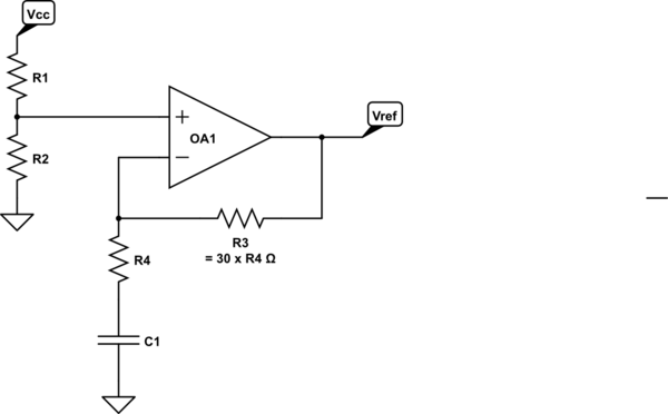
The following feedback topology might work.

schematic

simulate this circuit – Schematic created using CircuitLab

The idea here is that the feedback at DC gives near unity voltage feedback, making it useful for a DC buffer. However, as the frequency increases, the feedback ratio (\$\beta\$) falls, which will usually make the op-amp more stable.

The AC gain will increase as \$\beta\$ decreases, however, since input and your desired output are both DC, this higher gain will (hopefully) only affect noise. With 30 x noise over a simple unity gain buffer, this may or may not be an adequate solution to your problem.

\$\endgroup\$

Your Answer

By clicking “Post Your Answer”, you agree to our terms of service and acknowledge you have read our privacy policy.

Not the answer you're looking for? Browse other questions tagged or ask your own question.