25
\$\begingroup\$

I've researched and it says that resistors limit the current flowing through the LED.

But this statement confuses me because we know that in a series circuit, the current is constant at every point, so how come a resistor can limit the current flowing?

\$\endgroup\$
1

7 Answers 7

38
\$\begingroup\$

LEDs have a fairly constant voltage across them, like 2.2V for a red LED, which only slightly rises with current. If you supply 3V to this LED without series resistor the LED will try to set for a voltage/current combination for this 3V. There's no current that goes with this kind of voltage, theoretically it would be 10s, maybe 100s of amperes, which would destroy the LED. And that's exactly what happens if your power supply can supply enough current.
So the solution is a series resistor. If your LED needs 20mA you can calculate for the red LED in the example

\$ R = \dfrac{\Delta V}{I} = \dfrac{3V - 2.2V}{20mA} = 40 \Omega\$

You may think that supplying 2.2V directly will also work, but that's not true. The slightest difference in LED or supply voltage may cause the LED to light very dim, very bright, or even destroy. A series resistor will ensure that slight differences in voltage have only a minor effect on the LED's current, provided that the voltage drop across the resistor is large enough.

\$\endgroup\$
2
  • 13
    \$\begingroup\$ +1 because I once assumed that a LED would provide enough internal resistance and ended up with explosive shrapnel very nearly missing my eye. \$\endgroup\$
    – fluffy
    Commented Mar 20, 2012 at 22:53
  • \$\begingroup\$ What happens if the resistor is insufficient? For instance, let's say we're using a 10Ω resistor in this example. Will there be 80mA drawn through the circuit, or would it still be around 20mA, resulting in 2.8V going through the LED and potentially damaging it? \$\endgroup\$ Commented Feb 9, 2022 at 0:45
14
\$\begingroup\$

The point is a LED is a diode anyway and diodes have very small internal resistance (in "forward" direction of course), so unless there's something else in series the overall resistance is very low and the current is barely limited and this barely limited current can damage the LED and overload the circuit that powers it.

So yes, you're totally right that the current is the same in each point of the circuit when elements are connected in series, but when you add a resistor you increase the overall resistance of the series and this decreases the current.

\$\endgroup\$
7
  • 1
    \$\begingroup\$ Note that constant current around a loop is only for a relatively small subset of possible circuits. It is an OK assumption for this example but a dangerous one in general. \$\endgroup\$
    – Russell McMahon
    Commented Mar 20, 2012 at 11:21
  • \$\begingroup\$ @Russell McMahon: I don't get it at all. Which assumption do you mean? \$\endgroup\$
    – sharptooth
    Commented Mar 20, 2012 at 11:27
  • \$\begingroup\$ Re subset of circuits - anyhing with reactive components and AC or time varying anything will be able to have different currents at different places in a loop at any given time. An oscillator with eg series LC would probably be a useful example. You understand that such things can happen even if we don't usually put things in those terms but a raw beginner will have no concept of AC operation etc. \$\endgroup\$
    – Russell McMahon
    Commented Mar 20, 2012 at 11:39
  • 4
    \$\begingroup\$ @RussellMcMahon If I intended it correctly, I have to disagree: no matter how fancy are the components, the current in a branch (set of components in series without other wires getting in or out), the current will be equal everywhere. \$\endgroup\$
    – clabacchio
    Commented Mar 20, 2012 at 12:23
  • 1
    \$\begingroup\$ @PortreeKid see the comment in Russel's answer: you have to consider each component in the series as a whole, because what happens inside breaks the rule of a closed system \$\endgroup\$
    – clabacchio
    Commented Mar 21, 2012 at 13:32
6
\$\begingroup\$

Always with the complicated answers ;-). Look at it this way. What happens when you put a wire across the terminals of a battery? In a perfect world you get infinite current which melts the wire. We call this a short curcuit. Because diodes are designed to have minimal forward resistance we get the same effect as a short. Put a resistor in there to provide something to resist against current to limit it down from infinity

\$\endgroup\$
4
  • \$\begingroup\$ This may be understood and your question may have been rooted as a diode in a curcuit with other components that are limiting current by their resistance. While you may get a way with this - if anything changes in the curcuit, the LED is on it's own. Best to have its own R \$\endgroup\$ Commented Mar 21, 2012 at 21:29
  • \$\begingroup\$ How can u say tht the wire is experiencing knfinite current? Why infinite in the first place? \$\endgroup\$ Commented Mar 21, 2012 at 22:31
  • \$\begingroup\$ A bit simplicistic for an engineering site, and a subset of sharptooth's answer...welcome anyway! \$\endgroup\$
    – clabacchio
    Commented Mar 21, 2012 at 23:42
  • \$\begingroup\$ If we have infinite current, wouldnt that mean the wire isnt providing any resistance at all and should therefore not heat up? In a perfect world that is. \$\endgroup\$ Commented Jun 6, 2023 at 21:37
3
\$\begingroup\$

Imagine that

  • You had a water powered motor whose speed was proportional to current flow.

  • The motor itself offered very little resistance to current flow - you had to control the current flow external to a pump.

  • You has a pump able to pump 10 litres per second through a 10 metre pipe to the motor then through the motor and then through another 10 metre pipe to the suction side of the pump. (Flow rate was related to the pressure that the pump made and pipeline resistance - ie NOT a positive displacement pump.

  • When the pump was operated you found that the motor ran MUCH too fast and that you needed to limit flow to about 1 litre/second.

To achieve the requirement you could place a reducing valve in the circuit to drop most of the pressure and to limit the flow. The valve worked to drop a certain amount of pressure across it at a given flow rate and as adjustable. (This is about how many rel water valves do work).

You could place the valve ANYWHERE in the circuit and it would achieve the desired result. It could be at the pump inlet or exit or at the motor exit or inlet or anywhere in either pipe.

This is a close analogy to you LED question. The current needs to be limited as it is too high without a limiter. The limiter may be placed anywhere in circuit.


With the Battery - resistor LED circuit

The LED has a certain defined voltage drop at a chosen current.
To be specific lets say that at 20 mA the LED drops exactly 3.00 Volt. This is typical of some modern LEDs.
If we wish to run the LED at 20 mA we MUST arrange for it to drop 3 V - not more and not less.
If we wish to use a 9V supply to operate the LED we N=MUST "get rid of" 9-3 = 6B somehow.
The resistor does this.
To drop 6V at 20 mA the resistor needed is R = V/I = 6 / 0.02 = 300 ohms.
In this example a 9V battery + a resistor + an LED will operate at 20 mA. The resistor can be placed before or after the LED. The current is dropped across it in either location.


It is not relevant to this question but extremely important to know that your statement that

  • "we know that series ciircuit, the current is constant at every point."

is incorrect.

There are many circuits where this is rue -but also many circuits where it is not true.
In DC circuits with only resistive components, such as this 1 LED, 1 resistor circuit, then it is true. BUT when there are reactive components present such as inductors and capacitors or certain other non linear elements then it is often NOT true.

\$\endgroup\$
5
  • 1
    \$\begingroup\$ I disagree with the last paragraph: in a series circuit (one wire in - one wire out) the current will be the same at every point outside the components (treating them as black boxes). \$\endgroup\$
    – clabacchio
    Commented Mar 20, 2012 at 13:56
  • \$\begingroup\$ Yes, I'm a bit confused. @Russell, could you give an example for a series circuit where current is NOT equal through all elements? \$\endgroup\$
    – exscape
    Commented Mar 20, 2012 at 17:10
  • \$\begingroup\$ @clabacchio: "constant" does not mean (only) "same at every point", can also means "same at every time" and that clearly is not true when considering step response of a circuit with complex impedances or response to a time-varying forcing function (source). It can also mean "independent of load changes", for example in a "constant-current source". The specific phrase "constant at every point" means that the parameter in question (current) IS a function of location and nothing else. \$\endgroup\$
    – Ben Voigt
    Commented Feb 1, 2017 at 7:35
  • \$\begingroup\$ @BenVoigt I think you miss the point of the question, which is how can a component limit the current of another. Russell has a point, but added a lot of detail which confuses the reader \$\endgroup\$
    – clabacchio
    Commented Feb 1, 2017 at 7:41
  • \$\begingroup\$ @clabacchio: Well, Russell did start that section off with "It is not relevant to this question". \$\endgroup\$
    – Ben Voigt
    Commented Feb 1, 2017 at 7:44
3
\$\begingroup\$

Let's focus on what is important here: The LED (which is a diode) characteristic curve. Please look at this image from wikipedia. As you can see, for positive voltages across the diode its current increases exponentially. Imagine now you connect your LED to a power supply without resistor. You would have to set the exact voltage across the diode to get the exact current you need to light up the LED. If for any reason your power supply increases a little bit above the voltage you need then the current will be exponentially higher than before which may (it will!) damage your diode. So, how can a resistor help us with this problem? FEEDBACK! One of the most important concepts in electronics! Let's go back to our example, and add a resistor in series with the diode and the power supply. Now, everytime your power supply exceeds its nominal voltage the diode will increase its current exponentially again, but because the current got higher the voltage across the resistor will be higher too, which means, the voltage across the diode will decrease, compensating the power supply voltage increase.

\$\endgroup\$
3
\$\begingroup\$

An LED is a diode made from a semiconductor material which generates photons of light when current flows through the material. The more current through the LED, the more light the LED will emit, the brighter it will be. However there is an upper limit which is the amount of current sufficient to damage the LED.

An LED offers little resistance to the current flowing through it. Most of the little resistance it offers comes from the energy lost from the emitted light and the photon generation is so efficient that the resistance is pretty negligible. However as current increases, increasing the amount of light, the LED will at some point fail because the amount of current going through the LED causes material failures. With sufficiently large amounts of current, catastrophic material vaporization may result in what amounts to a small explosion within the LED exterior envelope. With the lower current levels found in 3.3v or 5v digital circuits the most likely result is the semiconductor material fails and stops conducting and the LED no longer glows.

How does circuit voltage affect the current draw of an LED? Since an LED is a type of diode, the Shockley diode equation describes the current a diode allows at various levels of voltage. The equation shows that the results of the Shockley function for a given range of voltage follows an exponential curve. This means that small changes in voltage can make large changes in current. So using an LED in a simple circuit whose voltage is higher than the LED's Forward Voltage risks having the LED draw surprisingly more current than its recommended levels resulting in LED failure.

See Wikipedia topic LED Circuit as well as Wikipedia topic Shockley diode equation.

So the idea is to engineer the LED circuit so as to limit the amount of current flowing through the LED. We want to balance out having enough current to cause the level of brightness desired without having so much that the LED material fails. The most common method of limiting current is to add a resistor to the circuit.

An LED should have a data sheet that describes the LED's electrical characteristics and tolerances. For example see this data sheet Model No.: YSL-R531R3D-D2.

The first characteristics we are interested in is (1) what is the maximum current that the LED can sustain before material failure is possible resulting in LED failure and (2) what is the recommended current range. These and other Maximum Ratings for a typical standard red LED (different LEDs will have different values) are in a table as duplicated below.
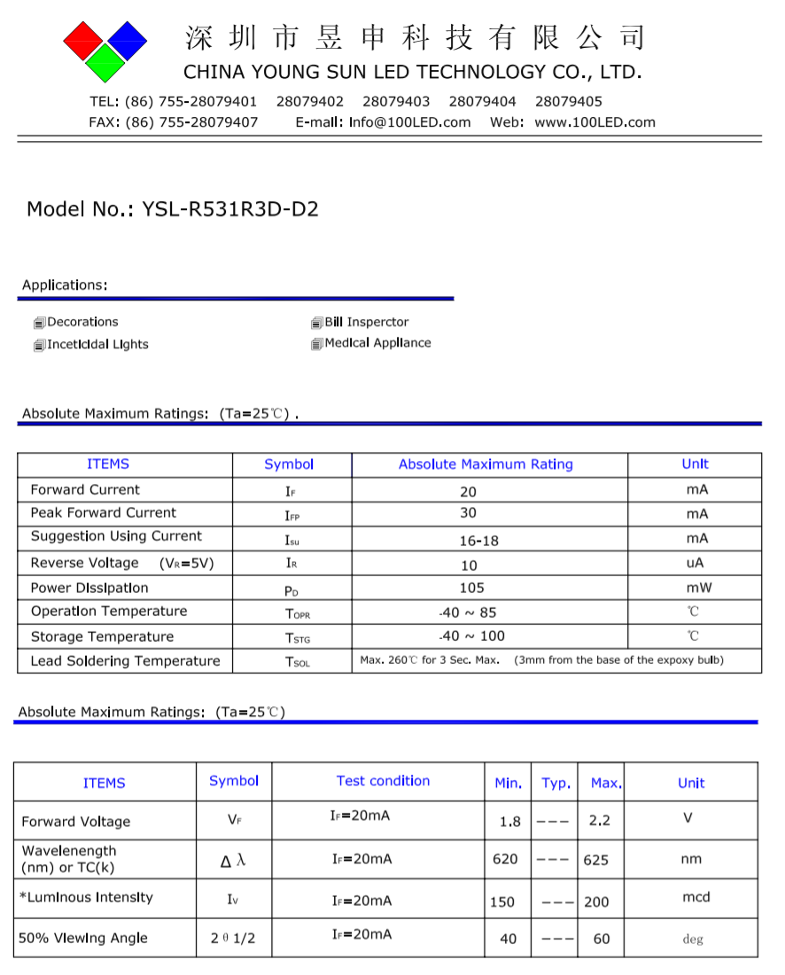
screen shot of standard red LED data sheet

In the table from the data sheet for this standard red LED we see that the maximum current is 20mA with the recommended range being 16mA to 18mA. This recommended range is the current for the LED to be at its brightest while not risking material failure. We also see that the rated Power Dissipation is 105mW. We want to make sure that in our LED circuit design we stay within these recommended ranges.

Looking in the next table we find a Forward Voltage value for the LED of 2.2v. The Forward Voltage value is the voltage drop when current is flowing through the LED in the forward direction, from anode to cathode. See What is “forward” and “reverse” voltage when working with diodes?.

If we were to use this LED in a circuit with 2.2v and a current of 20mA then the LED will dissipate 44mW which is well within our power dissipation safety zone. If the current changes from 20mA to 100mA the dissipation will be 5 times greater or 220mW which is well above the rated 105mW Power Dissipation for the LED so we could expect the LED to fail. See What happens to my LED when I supply too much current?.

To reduce the current through the LED to the recommended levels, we will introduce a resistor into the circuit. What value resistor should we use?

We calculate a resistor value using Ohms Law, V = I x R. However we will make an algebraic transformation because we want to solve for Resistance rather than Voltage so we instead use the formula R = V / I.

The value for I, current in amperes, is fairly obvious, lets just use the recommended minimum of 16mA or .016A from the LED data sheet in the transformed formula. But what value should we use for volts, V?

We need to use the resistor's voltage drop which is the contribution the resistor makes to the total voltage drop of the entire circuit. So we will need to subtract the voltage drop contribution of the LED from the total circuit voltage to determine the voltage drop contribution needed from the resistor. The voltage drop of an LED is the forward voltage value, the voltage drop in a forward direction from anode to cathode, from the table above.

For a standard Raspberry Pi project using the 3.3v rail as a power source, the calculation would be (3.3v - 2.2v) / .016A = 69 ohms (rounding 68.75 up)

So why is a resistor value such as 200 ohms commonly used when the calculations indicate 69 ohms?

The easy answer is that a 200 ohm resistor is a common resistor included in many experiment kits. We want to use a common resistor if the light emitted by the LED will not noticeably decrease.

So if we change from a 69 ohm resistor to a 200 ohm resistor, what is the change in the current? Again we use Ohm's law this time to solve for current in the circuit, I = V / R or 3.3v / 200 ohms = .0165A and when we look at the LED data sheet we see that this value is in the recommended range of 16 mA to 18 mA so the LED should be sufficiently bright.

\$\endgroup\$
-2
\$\begingroup\$

Simply ,the led have a low resistance ,if connected to a battary alone the current flowing through it will be very high (I=V/R) , high current means more dissipated power in the small led's resistance, which leads to burninng the diode (thermally), because the material have very low heat transfear constant .

Note that dissipated power =(I^2 ×R).

\$\endgroup\$
1
  • 4
    \$\begingroup\$ Sorry, the idea of LED's dissipating power as I^2*R assumes Ohms law, which does not hold. Power dissipation strictly speaking is V*I, and for LEDs I rises much faster than V. \$\endgroup\$
    – MSalters
    Commented Jan 25, 2017 at 10:12

Your Answer

By clicking “Post Your Answer”, you agree to our terms of service and acknowledge you have read our privacy policy.

Not the answer you're looking for? Browse other questions tagged or ask your own question.