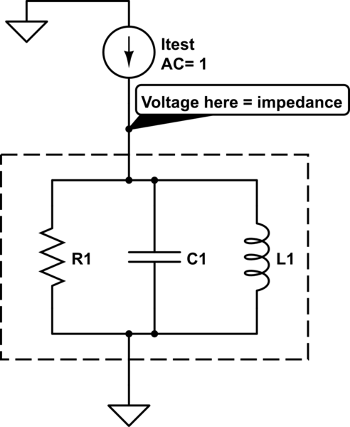
I need to build a bode plot that would show impedance curve of a simplest circuit for a frequency range of 0 to 20kHz. Apparently the x axis should be frequency, y axis should be impedance. I'd like to build one plot for impedance value and another for the phase. I'm using LTSpice IV at the moment.
-
2\$\begingroup\$ What is your question? Note also that a bode plot is for the gain and phase of a system. \$\endgroup\$– Andy akaCommented Sep 1, 2015 at 12:06
-
\$\begingroup\$ @Andyaka That is usually true but if that "gain" just happens to be in A/V (transconductance amplifier) instead of the usual V/V (voltage amplifier) then I could still make a bode plot. Same for V/A (impedance). Only the gain would have a different unit. But it would still be and look like a bode plot. \$\endgroup\$– BimpelrekkieCommented Sep 1, 2015 at 12:38
-
\$\begingroup\$ @FakeMoustache I am aware of what you say but I'm challenging the OP to think about what he really wants. Just call it my little suspicion he may want something else than what the question implies (6th sense). \$\endgroup\$– Andy akaCommented Sep 1, 2015 at 12:47
-
\$\begingroup\$ Andy aka, I'm just using a college book solving problems. It has a simple parallel circuit (cap and resistor) and I just need to build a graph that shows how the impedance (with the phase) changes in a frequency range from 0 to 20kHz \$\endgroup\$– BarbarisCommented Sep 1, 2015 at 16:15
-
\$\begingroup\$ In this simple case (grounded R in parallel to C) you simply must determine the input impedance of the circuit. That means: The procedure as described in my detailed answer is not necessary. \$\endgroup\$– LvWCommented Sep 1, 2015 at 18:47
2 Answers
What is Impedance ? As far as I know: Z = V/I
So if you fix I = 1 (Current source with AC = 1) and plot the voltage you plot V / 1 = ... ?
Aha V / 1 = V = Z !
This is how I simulate and plot the impedance over frequency of some DUT:

The magnitude will be the impedance The phase you can also plot directly.
If this puzzles you: Imagine in the box there is only a 1 ohm resistor. What would the plot be ?
Now a 10 ohms resistor...
Now a capacitor...
etc...
-
\$\begingroup\$ As far as I can see, this method can be used for determining the input impedance (against ground potential) of a two-pole only. \$\endgroup\$– LvWCommented Sep 1, 2015 at 12:36
-
\$\begingroup\$ Not true, the ground is only there because the simulator needs a reference. You can replace the ground by anything you want but then you would have to plot the difference between the voltage at both nodes of the impedance. Unless there needs to be some DC biasing voltage, I would not do that as it complicates things (and I'm lazy). \$\endgroup\$ Commented Sep 1, 2015 at 12:42
-
\$\begingroup\$ Yes - that`s what I have written in my answer. \$\endgroup\$– LvWCommented Sep 1, 2015 at 13:29
-
\$\begingroup\$ Looks good. Which tool did you use ? And can you show the resulting plot ? I tired that in LTSpice IV but the plot did not have a curve as well as I did not know how to display the phase. \$\endgroup\$– BarbarisCommented Sep 1, 2015 at 16:17
-
\$\begingroup\$ I can do this with Cadence Spectre (professional circuit simulator) or QUCS. This is a very basic simulation, LTSpice should be able to do this. I don't use LTSpice so I can't give you any hints other than: read the manual. No curve then perhaps you should simulate from 1 Hz to 100 MHz and see if there's a curve. \$\endgroup\$ Commented Sep 1, 2015 at 17:52
The impedance between two points in a circuit is defined as the complex voltage-to-current ratio (voltage between the two points and current through the connecting part). After performing an ac analysis it shouldn`t be a problem to display (a) the magnitude of this ratio in dB and (b) the phase difference of this ratio (between those two points).
Simplification: Because there is no phase shift - as far as the current is concerned - between the two points defining the impedance, you simply can use the phase difference of both node voltages.
-
\$\begingroup\$ Can you share how to do that in LTSpice ? In a form: select that, add this, etc. \$\endgroup\$– BarbarisCommented Sep 1, 2015 at 16:19
