I have a pulse signal at 1 hz which goes high +5V and low 0V. How do i turn it into a continuous one? +5V. i have searched in different places and what i found says that there are different methods such as using an op amp as an integrator, then i also found that it can be used a diode, resistor and a capacitor, others suggest that a sample and hold circuit can also work. However none of these answers seem to be clear to me. i am still a novice in this matter. Would somebody help me with an answer that has a schematic i could test?. I have also found that a retriggerable monostable can work but i am not sure if this is the right approach, as i need the "continuous signal" to go low immediately after the input pulse is interrupted. If possible i would like to do this using logic gates such as the ones found within 4000 cmos series. Thanks for taking your time reading my doubt.
-
5\$\begingroup\$ You can't have "immediately" unless your circuit is psychic. \$\endgroup\$– Ignacio Vazquez-AbramsCommented Apr 29, 2016 at 8:23
-
2\$\begingroup\$ How can you possibly know that the pulse train has been interrupted before the next pulse fails to arrive? \$\endgroup\$– Ignacio Vazquez-AbramsCommented Apr 29, 2016 at 8:35
-
2\$\begingroup\$ The answer is to wait until you fail to receive the next pulse. \$\endgroup\$– Ignacio Vazquez-AbramsCommented Apr 29, 2016 at 8:41
-
1\$\begingroup\$ The easiest way is to probably use a microcontroller. Sample the pulse signal at atleast 2Hz. When the pulse signal no longer alternates adjust your output as necessary. I know you asked for discrete ics and not programmable, but this is the easiest way. \$\endgroup\$– Adam ZCommented Apr 29, 2016 at 8:47
-
1\$\begingroup\$ The closest you can get to "immediately" is one pulse length. If your pulse is once per second, then you can only tell that it has failed to arrive by waiting that 1 second to see if it pulses again. At the end of the one second with no pulse, you know that there was an interruption. You cannot tell immediately if the pulse is gone because it isn't there most of the time anyway. That's why the jokes about psychic circuits. A 555 wired for retriggerable monostable operation with a time of just over 1 second is probably the cheapest solution. \$\endgroup\$– JRECommented Apr 29, 2016 at 9:13
4 Answers
You are failing to see the error in your belief.
If the pulse is high (as normal) and then goes low (as normal) and while low it is "interrupted", the signal will still be low and you won't have known the signal was interrupted until you realize that it has failed to go back high some time later.
It's like when your phone rings - it does so in bursts - you go to pick it up when the bell falls silence but you don't actually know that the person ringing you has hung up during that silence.
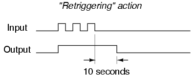
So forget about "immediately" and use a re-triggerable monostable. Here's the waveforms: -
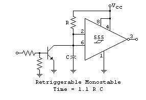
Here's a retriggerable monostable circuit: -
Picture stolen from here. Basically, a re-occuring pulse fed to the input (the little circle to the left in front of the two resistors feeding a BJT) keeps the 555 from timing out.
-
\$\begingroup\$ Nice handy circuit. But is there any other options other than 555?. Btw thanks. The foreword about pulses pretty much explained me what i was wrong. \$\endgroup\$ Commented Apr 30, 2016 at 23:43
-
\$\begingroup\$ There are many options and there are logic devices that are monostable. A diode, capacitor, resistor and Schmitt trigger will also work. \$\endgroup\$– Andy akaCommented May 1, 2016 at 9:10
-
\$\begingroup\$ @ChrisSteinbeckBell if you are done with this Q and A then please consider formally accepting an answer. It doesn't have to be mine and also, if there's still something you don't know that is related to this Q then leave a comment. \$\endgroup\$– Andy akaCommented Oct 31, 2020 at 11:33
If you have a 1 Hz square wave (high 500 ms, low 500 ms), then it takes at least 500 ms to tell that the pulses have stopped. You can't tell "immediately" that the signal has stopped.
When the signal goes low, for example, you have no way of knowing the difference between the signal having gone away, or just entering the low phase. You can only tell after 500 ms because then the real signal will go high, but if the signal went away then the voltage will stay low.
In any case, to turn a pulse train into a continuous signal (within the fundamental constraint described above), you can use a retriggerable monostable multivibrator, more commonly referred to as a retriggerable one-shot. When this device is hit with a pulse, its output goes on. With no other input, it stays on for some time, then turns off after the delay time has elapsed. The "retriggerable" part means that if it is hit with another pulse while on, the delay until off time is reset and the output stays on longer.
In your case, you need to set the on-time at least as long as the maximum time between pulses. If the device only triggers on a particular edge, then that time needs to be at least one second. Of course you want to make it a little longer for some margin, like 1.2 seconds or 1.5 seconds.
-
\$\begingroup\$ This pretty much reaffirms what others have mentioned above so thanks for clarifying this for me. i am still a novice. Anyway, but why when i tried to simulate this it didn't behaved as stated?. Am i making a mistake?. I am trying to do this with a 4538. \$\endgroup\$ Commented Apr 30, 2016 at 23:58
" I would like to do this using logic gates such as the ones found within 4000 cmos series."
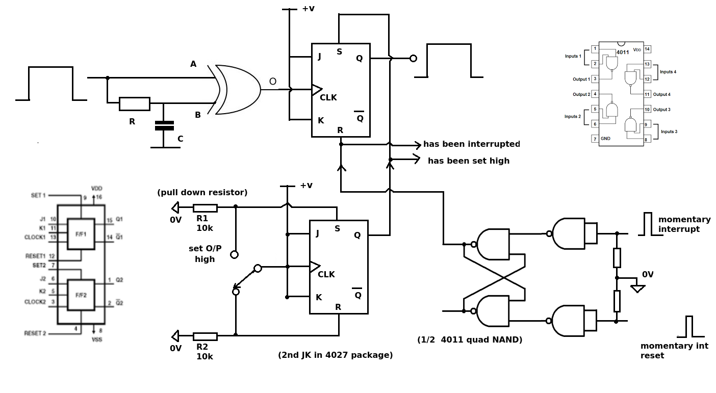
Using and EXOR gate (4070) and an RC delay you can separate the incoming 1 Hz clock into its edges to give very narrow pulses at twice the frequency (2Hz).
Then a JK flip flop (4027) can recombine the two pulses back to the original 1Hz clock.
Now you have access to the SET and RESET inputs of the JK flip flop wich will allow you to set the output HIGH or LOW and monitor these control signals as the RS inputs override the incoming clock.
-
\$\begingroup\$ Do we mean t=RC right?. So if R and S are "grounded" by a 10k resistor, does this means the output at Q would be a straight pulse?. Sorry but i got lost during the paragraph after recombining the two pulses. \$\endgroup\$ Commented Apr 30, 2016 at 23:53
-
\$\begingroup\$ Yes. The values of R and C give a time constant which controls the delay after the edges of the incoming pulse. The values you choose will determine the actual width of pulse at the XNOR gate output. With the values given this will be about 7 - 10uS. The JK flip flop converts the two short pulses back to the original 1Hz pulse. Both the Set and Reset are normally held LOW with 10k resistors. With no 'interrupt' or 'setting the output low' the Q output will be the 1Hz pulse. Keeping the Reset High will put (and keep) the Q output Low (no pulse). Keeping the Set High does the opposite. \$\endgroup\$ Commented May 2, 2016 at 13:31
-
\$\begingroup\$ I tried this circuit on PSPICE but it didn't worked as i expected. The output keeps the pulse at 1 hz and is not a straight +5dc line. What am i doing wrong?. \$\endgroup\$ Commented May 2, 2016 at 19:47
-
\$\begingroup\$ @ChrisSteinbeckBell Either the P-Spice model does not model this chip or you are using a narrow pulse to control the Set or Reset so when it returns to LOW the 1Hz pulse starts again. I've edited the diagram to show a bit of glue logic to allow the use of narrow pulses to control the S-R inputs. \$\endgroup\$ Commented May 3, 2016 at 9:45
-
\$\begingroup\$ You're right, after further investigation i found that my pspice software had not modeled the chip i was using. I had to try it on the breadboard and use the advice you mentioned. Thanks for clarifying your diagram. i can't use the up arrow on your comment, but your response is the one that helped me the most. \$\endgroup\$ Commented May 14, 2016 at 19:50
Can't a simple grounded capacitor of 1 uF or 0.1 uF between the input line and ground do the trick? It would cause a small delay thought. Not exactely "immediately". The higher the value of the capacitor, the longer the delay.


