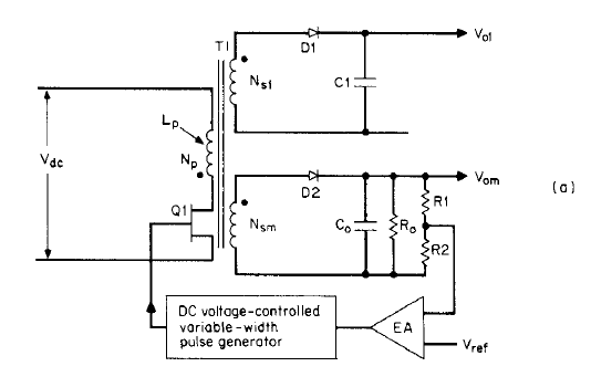
From what I understand, when the MOSFET is ON, the output diode (D1) is reverse biased. Then when the MOSFET turns off, the magnetic field of the transformer collapses and provides power through the output diode and into the load. However if there is no load at the output, then when the MOSFET is off, the magnetic field in the inductor has no where to go, and so it would build up an extremely high voltage across the MOSFET. Wouldn't this then damage the MOSFET? How do power supplies prevent this from happening?
-
\$\begingroup\$ Potentially yes. But see R0 on the other secondary. \$\endgroup\$– user16324Commented Oct 25, 2021 at 14:43
-
\$\begingroup\$ and so it would build up an extremely high voltage across the MOSFET. Wouldn't this then damage the MOSFET? Of course it would. So the MOSFET will need protection. All MOSFETs have a Drain-Source (actually not Source but Bulk, which is shorted to the Source) diode which will limit the voltage as the polarity of the voltage will reverse (the \$V_{DS}\$ of the MOSFET will be negative. Also there will be a snubber network. \$\endgroup\$– BimpelrekkieCommented Oct 25, 2021 at 14:51
-
\$\begingroup\$ In additi0n to R0 mentioned above, if the converter is designed to withstand open output (I would hope so), then the caps will slow the rise in voltage enough that the controller has time to react before the voltage rises too much. \$\endgroup\$– Math Keeps Me BusyCommented Oct 25, 2021 at 14:53
-
\$\begingroup\$ Another things is that the system has feedback, it will sense through the feedback winding (the one connected to D2) that there is less load at the output (\$V_{om}\$ will increase) so less energy will be pumped into the transformer by making the pulses on Q1 shorter. \$\endgroup\$– BimpelrekkieCommented Oct 25, 2021 at 14:54
-
\$\begingroup\$ Without feedback and duty high enough the output voltage will extremely rise. With feedback the control loop decreases the duty to sufficient value to keep the output regulated (like in loaded state). \$\endgroup\$– user208862Commented Oct 25, 2021 at 15:02
2 Answers
However if there is no load at the output, then when the MOSFET is off, the magnetic field in the inductor has no where to go, and so it would build up an extremely high voltage across the MOSFET
Nearly there.
The inductor charges the output capacitor to a higher voltage and, if something doesn't take control of the duty cycle (such as the control loop shown in your picture formed by the error amplifier), then it ends in tears.
How do power supplies prevent this from happening?
The error amplifier and feedback prevent this from happening by reducing the duty cycle to zero. Now, the output stays at the target voltage and the MOSFET stops switching until a load is reconnected to the output.
-
\$\begingroup\$ So if the output capacitor is undersized, then could it saturate before the feedback loops kicks in to reduce the duty cycle? Also, if the ESR on the output capacitor is high, would this "redirect" current back onto the MOSFET? \$\endgroup\$– willieb3Commented Oct 25, 2021 at 15:24
-
1\$\begingroup\$ @willieb3 capacitors don't saturate. The feedback loop must have enough bandwidth to cope with the situation. Current can't go to the MOSFET from the capacitor because of the diode. \$\endgroup\$– Andy akaCommented Oct 25, 2021 at 15:55
-
\$\begingroup\$ @Andyaka in case of no feedback loop the MOSFET should burn out due to the high voltage but what's happening in this case. youtu.be/okzxk1almeA?si=wR9PUqzSN3zFAIIz. In this tutorial can see a very high voltage at the output side but still the MOSFET is working fine....how? \$\endgroup\$– kam1212Commented Oct 25, 2023 at 11:11
A so-called indirect energy transfer converter cannot operate without load. This is true for a boost, buck-boost or flyback converter. This is because at each turn-on event, you store energy in the primary inductance of the flyback transformer and, at the switch opening, this energy has to go somewhere. If there is no load to absorb the power generated cycle-by-cycle, then the output voltage increases until something breaks. It can be the output capacitor venting out, the primary-side MOSFET blowing up because you exceed its \$BV_{DSS}\$ or the secondary-side diode whose breakdown voltage is violated. This is a typical case when the converter runs in open-loop, for instance if the optocoupler is destroyed.
In a true no-load condition, the converter will try to reduce its duty ratio as much as it can. However, in current-mode control which is the most popular control method, the minimum pulse width is constrained to the sum \$t_{prop}+t_{LEB}\$ which can be as high as 150 ns + 250 ns = 400 ns. \$t_{prop}\$ represents the time to shut down the power switch when the CS comparator detects the peak value and \$t_{LEB}\$ designates the leading-edge blanking time needed to cleanse the current spike. For a 100-kHz converter, it can amount to a minimum duty ratio of 0.4/10 = 4% which is not that high but still large. So if a converter is left in a no-load condition with such a minimum duty ratio, what is going on? Well, if you are lucky enough that the natural output load (the optocoupler bias current, the resistive divider, a potential bleeder) absorbs the energy in this mode, you are safe. If not, then the voltage will inexorably increase, going back to the situation I described before.
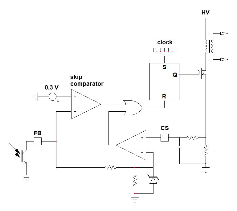
Some controllers can go down to true 0% duty ratio and the venerable UC384x is one of them. For the other ones, one very simple mechanism is called skip cycle. An extra comparator is installed in the circuit, observing the feedback voltage (FB). When the feedback voltage is high enough, the skip comparator is silent. When the FB voltage decreases too much (300 mV typically) and tends to impose too low a peak current, approaching the minimum pulse width, then the skip comparator kicks in and resets the PWM latch, stopping all pulses:
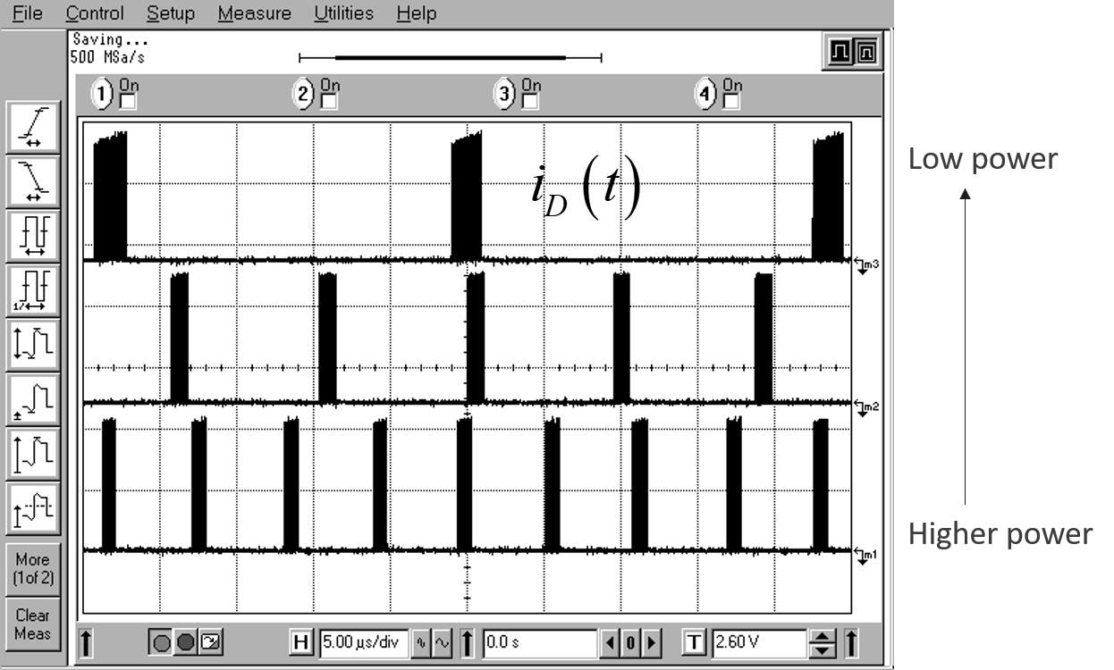
This technique is now very popular and found in almost all ac-dc offline controllers. New techniques have emerged to reduce the acoustic noise as pulse bunches can excite the transformer which becomes a transducer. Typical operating waveforms are shown below:
With this technique, you can safely operate down to 0 A and reduce the standby power to the lowest value, typically below 100 mW at a 230-V rms voltage.
-
\$\begingroup\$ @Ultra67 thanks for chasing the typo! \$\endgroup\$ Commented Nov 16, 2021 at 22:02


