1
\$\begingroup\$

I am designing a 30 V 5 A lab bench power supply having SMPS as a pre-regulator for the linear stage which will keep the SMPS output always 4 V higher than the main output voltage. This means SMPS output will be varying from 4 V to 34 V. For SMPS, I have used forward topology and therefore it requires a minimum load to operate properly. After some trial and error in the simulation, I found out that it requires a 1.2 W minimum load at its output and therefore I want to have some margin and want to place a 2 W load at the output. But since the output voltage will be varying from 4 V to 30 V I can not just put a resistor at the output because if it is dissipating 2 W at 4 V then it will be dissipating 144.5 W at 34 V which is obviously not practical.

Is there any simple way that requires only a few components to overcome this problem?

EDIT: Extra details if required:

  1. I am using UC3844 as the controller IC. Link to datasheet.

  2. I have tried using opamp to maintain a constant voltage across a resistor and hence the power dissipated by it but the rest of the voltage is dropped across a BJT which is carrying the same current as of the resistor and therefore in total around 17 W (BJT and resistor combined) is dissipated at 34 V which is still pretty high.

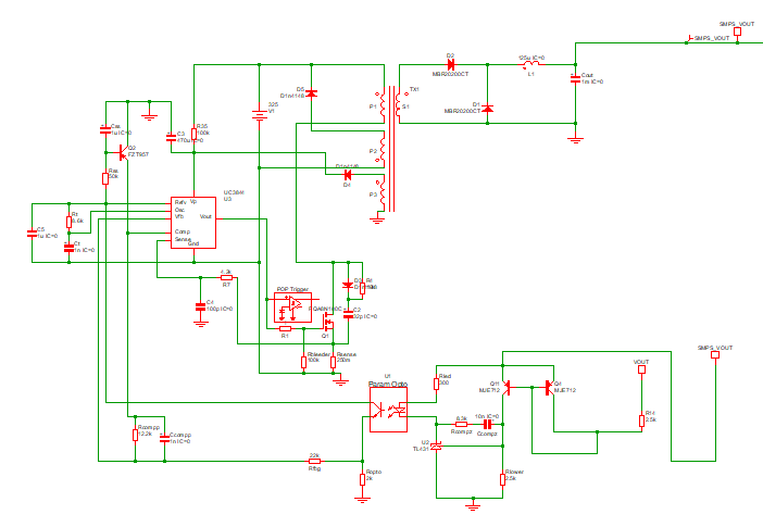
  3. This is my SMPS schematic:

enter image description here

\$\endgroup\$
7
  • 1
    \$\begingroup\$ ”forward topology and therefore it requires a minimum load to operate properly” If implemented correctly, it would be happy with no load. Fix that instead of putting a bandaid on it? \$\endgroup\$
    – winny
    Commented Dec 9, 2021 at 10:16
  • \$\begingroup\$ Maybe you have implemented a flyback converter - they require a minimum load usually. Be clear about this as winny implies. \$\endgroup\$
    – Andy aka
    Commented Dec 9, 2021 at 10:23
  • \$\begingroup\$ Where is the problem with pulse skipping? After implementation the SMPS must maintain constant output with 10k dummy load only. \$\endgroup\$
    – user208862
    Commented Dec 9, 2021 at 10:23
  • \$\begingroup\$ @winny Maybe I need to learn more about the forward converter but AFAIK if there is no load at the output, MOSFET will be switching with a very low duty cycle, and next to no power will be transferred to auxiliary winding and the control IC will shut down and will take some time to turn on again due to soft-start circuit. \$\endgroup\$
    – tinkerer
    Commented Dec 9, 2021 at 10:25
  • \$\begingroup\$ @Andy aka No I am pretty sure I have used forward converter \$\endgroup\$
    – tinkerer
    Commented Dec 9, 2021 at 10:25

2 Answers 2

2
\$\begingroup\$

Finally I found the solution. This is what worked for me.

My auxiliary winding's turns ratio was not correct. It was going into Under Voltage Lockout in no load condition. I played with the turns ratio of the auxiliary winding and managed to keep the UC3844 from going into Under Voltage Lockout and maintain the supply voltage within the recommended range as mentioned in the datasheet over the whole range of input voltage as well as in no load and full load conditions. Now there is no need to have any kind of dummy load at the output.

\$\endgroup\$
1
  • \$\begingroup\$ So, was your simulation also wrong? \$\endgroup\$
    – Andy aka
    Commented Dec 11, 2021 at 18:06
0
\$\begingroup\$

After some trial and error in the simulation, I found out that it requires a 1.2W minimum load at its output

A minimum load is needed on some topologies to prevent the output voltage rising above the upper limit. So, implement a variable voltage shunt regulator (fairly trivial) to keep the upper limit to whatever is needed. This will consume only the power it needs in order to keep the output voltage clipped at the right value. It fixes the problem more directly than trying to implement a constant power load.

\$\endgroup\$

Your Answer

By clicking “Post Your Answer”, you agree to our terms of service and acknowledge you have read our privacy policy.

Not the answer you're looking for? Browse other questions tagged or ask your own question.