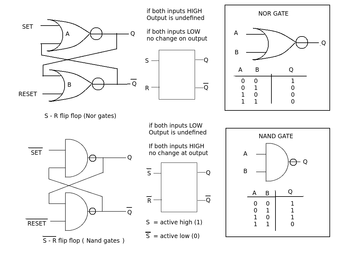
S - R (or R S) just means that we use a 'HIGH' or '1' to Set or Reset the outputs. The Set signal should make the Q output high and the Reset signal should make it low.
This operation can be done by cross connecting two NOR gates.
Another commonly used circuit is the NOT S R flip flop using NAND gates. Here the controlling input is a 'LOW' or '0' i.e. NOT '1'
This is constructed with two NAND gates.
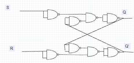
Now it is possible to construct NOR or NANDS from other gate combinations so that circuit diagrams may look a little different. For example you could add an inverter to the inputs of the NAND version and convert it to an S R type. By connecting the two inputs of a NAND gate you can make an inverter, so a 4 dual input NAND gate (e.g. 4011 or 7400) could be used to produce you S R flip flop.i.e 4 gates, not the 6 or 8 gates you think.
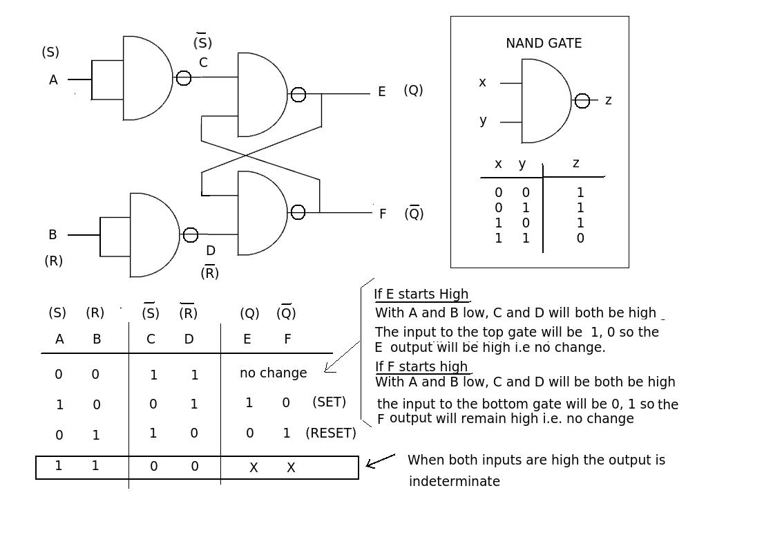
A walk through the circuit operation of the NAND S R flip flop (4 gates).
When both inputs are low the flip flop will be in one of two states, either the Q output is high or it will be low. In either case the low (0) inputs will have no effect and the outputs remain in their initial state.
Putting a '1' on input A ('0' on B) will cause a '0' input at C that will produce a '1' output at E (because any '0' input on a nand gate will produce a '1' output. The E output will place a '1' input onto the bottom gate. The other input is also '1' because the B input is '0'. The output of the bottom gate will then go to '0'. This '0' output (F) will keep the top gate output at '1' when the A input changes back to a '0'. The flip flop is now in the SET condition. (a '1' on the SET input has produced a '1' at the Q output)
Similarly if the B input is a '1' (A input '0') this will put a '1' at the F output. ,This will produce a '1 on the input to the top gate that combines with the other '1' at C to produce a '0' at the output. This '0' will keep the bottom gate output at '1' when the B input goes to '0'. The flip flop is now in the RESET condition. (a '1' on the 'REST' input has produced a '0' at the Q output)
As with all S R flip flops a problem arises when you try to SET and RESET the outputs at the same time. In this case both outputs will go to '1' and it will depend which input falls to '0' first as to how the state of the outputs will be determined.


