1
\$\begingroup\$

My doubt relates to a routing style of signals. Speed is not the criteria as the signals are not high speed. Kindly refer the image below please -
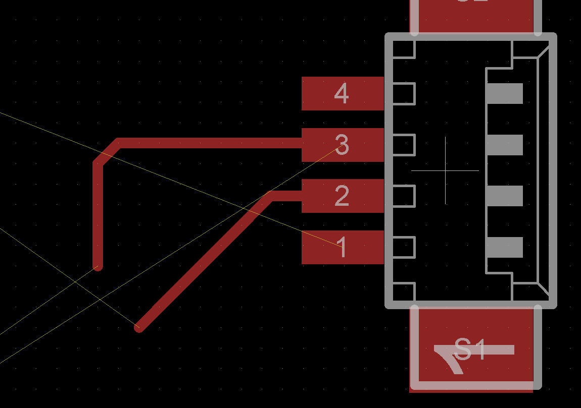
PCB tracks. There are 2 ways to route signals. They are both shown by me vis-avis pins 2 and 3. I feel its more apt to do it ibn the way done in pin 3 (in a more aesthetic sense) than the one done in pin 2. Which is more apt and technically so. Which style is more prevalant. As I mentioned, speed is not a conceern here. I merely dont have more signals crossing diagonally, but this means I might end up with longer signals. Is my approach right ? If not kindly advice the reasons please.

\$\endgroup\$
3
  • \$\begingroup\$ What earth plane regime are you using? What sources of cross-interferers might be present in the general locale of the tracks? What output and input impedances are associated with the tracks? \$\endgroup\$
    – Andy aka
    Commented Jan 22, 2016 at 11:00
  • \$\begingroup\$ @Andyaka. As I had mentioned, there is no high speed signals. IOt is a 2 layer board with GND pours on both sides. I am using standard track widths of 0.254mm and such. No complex signalling that would require controlled impedance please. \$\endgroup\$
    – Board-Man
    Commented Jan 22, 2016 at 11:07
  • \$\begingroup\$ I never assumed high speeds nor did I assume controlled impedances when I made the comment above. Given that I have explained myself maybe you can address the questions in the comment I made? \$\endgroup\$
    – Andy aka
    Commented Jan 22, 2016 at 11:21

3 Answers 3

2
\$\begingroup\$

Generally you want to keep the traces as short as possible. The trace coming off of pin 3 is actually slightly longer than the one coming off of pin 2, and thus is not generally preferred. It also takes up more space which means your PCB will likely have to be larger. A larger PCB will cost more in the long run. Usually you'll want to keep the board as small as possible (assuming you have that flexibility) and in order to do that you need to place components and traces as densely as possible (provided you keep interference between them to a minimum). The trace coming off of pin 2 is a much better choice for denser routing which will be cheaper overall.

\$\endgroup\$
1
\$\begingroup\$

With low speed signals, longer traces usually means higher noise reception.

If the signals does not have any close source of noise, or you don't need to use this circuit in a highly noisy environment (like an industry), you are pretty much free to do the routing that you prefer.

80 out of 100 times, for "casual" circuits, you won't have any problem with either routing, but a prototype is always the only way to be certain about that.

\$\endgroup\$
1
\$\begingroup\$

If the traces are carrying differential signals then keep them together, if single ended or unrelated, then gap is good to reduce cross-talk. If there are no other considerations then go for minimum length i.e. as pin 2. The problem that you may face with that, and the reason that pin 3 style may be beneficial is that if you optimize lengths too early in the layout process you end up cutting off routing paths and via space for other unrouted signals (e.g. pin 1). These days a good autorouter can do a much better job of balancing the conflicting requirements of track length, differential signals, length matching etc than you could hope to do by hand if the design is very complex. Sorry, this answer has turned into "it depends".

\$\endgroup\$
2
  • \$\begingroup\$ What is minimum gap recommended ? \$\endgroup\$
    – Board-Man
    Commented Jan 22, 2016 at 11:03
  • \$\begingroup\$ For low voltage signals that are differential, or where cross-talk is not an issue then its down to the PCB vendor's technology, 8thou is very common for general purpose and won't incur any price penalties. For differential signals that need a specific transmission line impedance then the gap needs to be right, there are lots of on line resources for calculating that. For cross talk issues it all depends on the signals and gets complicated. Cross talk can be magnetic of capacitive, but if your signals are all low speed it is unlikely to be an issue. \$\endgroup\$ Commented Jan 22, 2016 at 11:12

Your Answer

By clicking “Post Your Answer”, you agree to our terms of service and acknowledge you have read our privacy policy.

Not the answer you're looking for? Browse other questions tagged or ask your own question.